Product Overview
The PowMr POW-SunSmart 6.5KP PRO is an all-in-one hybrid solar inverter designed for home backup and off-grid systems. It delivers pure sine wave power in true split-phase (120V/240VAC) from a single unit, supporting both standard outlets and heavy 240V appliances. Featuring a touchscreen LCD for intuitive operation and real-time energy flow visualization, this inverter is compatible with various battery types including 48V Lithium (with CAN/RS485 BMS communication), Gel, Flooded, and AGM batteries.
- Output Power: 6500W continuous, 13000VA peak power.
- Dual MPPT: Two independent MPPT trackers, each with 18A current and 550V max input, supporting up to 10kW solar array.
- Parallel Operation: Supports parallel operation of up to 6 units for flexible expansion.
- Battery-Less Mode: Allows the inverter to operate with just solar or grid input without a connected battery.
- Time-of-Use (TOU) Scheduling: Program battery charging/discharging to maximize savings.
- Comprehensive Protection: Includes PV overvoltage, overload, short circuit, over-temperature, and anti-backfeed protection.
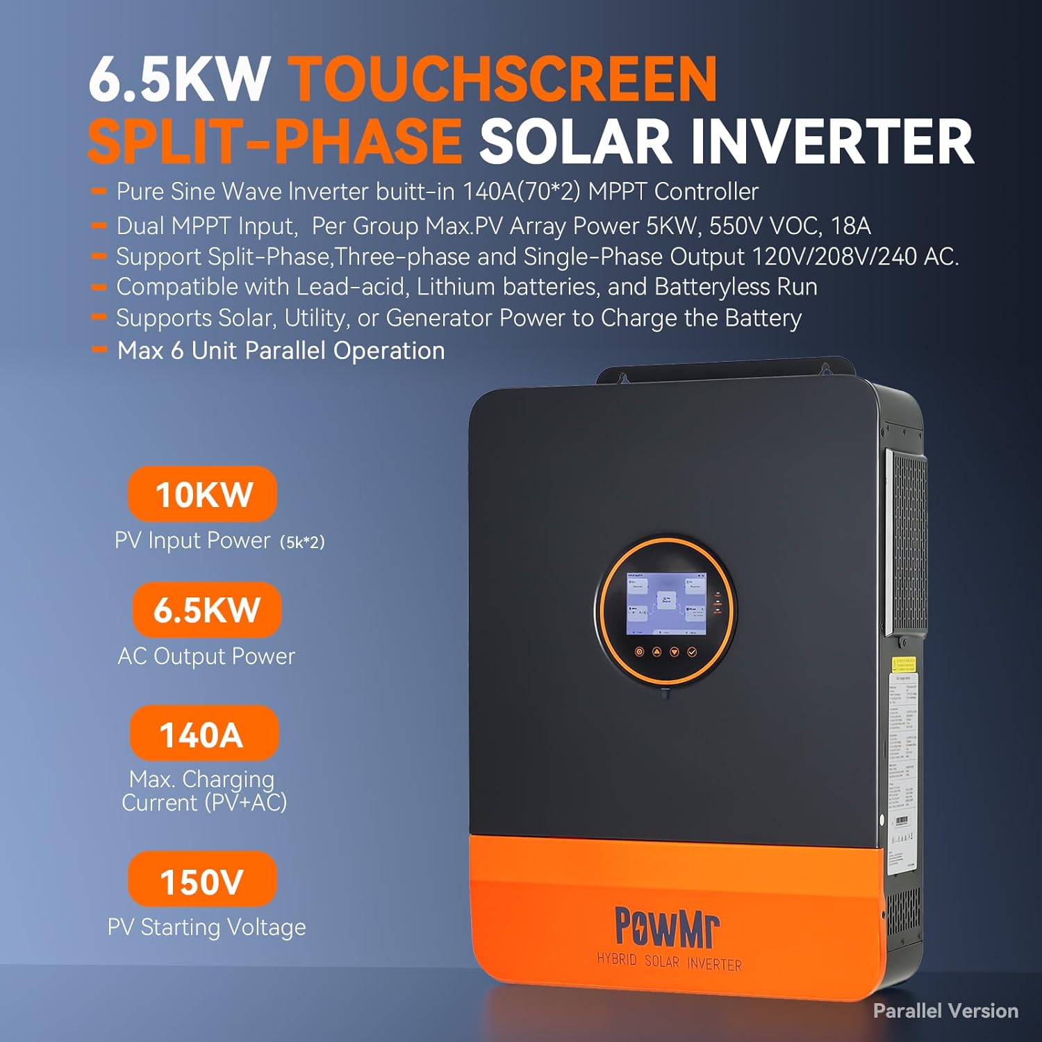
Image: PowMr 6.5KW Touchscreen Split-Phase Solar Inverter showing its features and specifications on the side label.
Setup
Physical Installation
Mount the inverter on a sturdy wall in a well-ventilated area. Ensure adequate spacing for heat dissipation. The dimensions are 21.8"L x 16.5"W x 5.2"H and it weighs 41.2 lbs. It is IP20 indoor rated.
Wiring Connections
All wiring should be performed by a qualified electrician following local electrical codes and safety regulations. Ensure all circuit breakers are in the OFF position before making any connections.
- Battery Connection: Connect the positive and negative terminals of your 48V battery bank to the inverter's battery terminals. Use appropriate gauge cables and ensure correct polarity. If your battery does not have a built-in low-voltage switch, install a DC circuit breaker between the battery and the inverter.
- PV Input Connection: Connect your solar panel arrays to the PV input terminals. The inverter supports dual MPPTs, allowing for two independent PV arrays.
- AC Input (Grid) Connection: Connect the utility grid (L1, L2, N, and PE wires) to the AC input terminals of the inverter through an appropriate AC circuit breaker.
- AC Output (Load) Connection: Connect your household loads (L1, L2, N, and PE wires) to the AC output terminals of the inverter through an appropriate AC circuit breaker.
- Grounding: Ensure the inverter chassis is properly grounded. The grounding wire should not pass through the ATS but connect directly to the load's grounding line.

Image: Diagram illustrating the pure sine wave output of the inverter, providing 120V and 240V to various home appliances simultaneously.
Current Transformer (CT) Installation
Mount the CT labeled "L1" on the L1 wire between the utility meter and the AC input breaker. Do the same with the CT labeled "L2" on the L2 wire. Ensure the arrow on the CT is pointing toward the inverter. Plug the CT communication cable into the CT port at the bottom of the inverter. This setup allows devices connected to the AC input line to safely use excess solar power, preventing power from feeding back into the grid.
Video: This video demonstrates the AC input load and CT installation process for the 6.5KP inverter, showing how to connect the utility lines and current transformers to monitor energy flow and prevent backfeeding to the grid.
Parallel Operation Setup
The inverter supports parallel operation of up to 6 units. When connecting multiple inverters in parallel, it is crucial to ensure that the cable lengths from each inverter to the busbars are identical to avoid current imbalance, which can lead to varying voltage drops and affect system efficiency and reliability. Use two busbars for the positive and negative terminals, allowing all parallel inverters to connect to the same battery. Connect the battery pack to the busbars, ensuring correct polarity. If your battery does not have a built-in low-voltage switch, install a DC circuit breaker between the battery and the busbars.
Video: This video provides a detailed parallel wiring guide for the POW SunSmart 6.5KP solar inverter, demonstrating how to connect multiple units for increased power output.
Automatic Transfer Switch (ATS) Connection
The main role of an ATS in an inverter system is to act as a second-level switching protection device. Although the inverter itself already includes an internal transfer switch to maintain stable AC output, an external ATS provides additional backup protection. In situations where the inverter stops supplying power due to low battery voltage or unexpected faults, the ATS ensures your loads can still receive power by automatically switching to an available source.
For exact wiring instructions, always refer to the wiring diagram provided with your specific ATS product. In general, connect the inverter's AC output to the main power input of the ATS and connect the utility grid to the backup power input. The two output terminal sets of the ATS will be connected in parallel, then wired to the load circuit. Note that the grounding wire does not pass through the ATS; connect it directly to the load's grounding line.
Video: This video explains how to boost the reliability of the 6.5KP inverter system by connecting an Automatic Transfer Switch (ATS).
Operating Instructions
Powering On/Off
After completing all connections, close the battery circuit breaker and then power on the inverter. Once the inverter begins normal output, you will see the main power indicator on the ATS light up, and the light bulb (if connected as a visual load) will turn on. Next, turn on the utility power. The backup power indicator on the ATS will light up. Then, by opening the battery circuit breaker and shutting down the inverter, the ATS will automatically switch the load to utility power.
Touchscreen LCD & App Monitoring
The inverter features an intuitive LCD touchscreen with real-time energy flow visualization. You can see exactly where power is coming from and where it’s going, and adjust settings with one tap. For remote monitoring and control, download the SmartESS App from the App Store or Google Play. Note that the Wi-Fi/GPRS data acquisition module needs to be purchased separately.

Image: Screenshots of the SmartESS App interface showing energy monitoring and control features for the PowMr inverter.
Flexible Time-of-Use Settings
Program the Time-of-Use (TOU) schedule to charge your battery during low-rate periods and power your home when rates peak, maximizing savings automatically. The system supports up to 5 user-defined time slots for flexible scheduling of battery charging and discharging.

Image: Diagram illustrating the flexible Time-of-Use settings for optimizing energy efficiency and reducing costs by scheduling battery charging and discharging.
Configuration Settings
To access the settings menu, press the SET button on the inverter's touchscreen. Settings for parameters 31 and 68 can be configured before the inverter enters inverter mode (in standby mode) or by turning off the rocker switch to stop inversion. These settings cannot be changed while the inverter is running. It's best to configure parameter 68 first, as selecting "180" for parameter 68 will prevent you from choosing 2P or 3P in parameter 31.
- #01 Output Power Priority: Configures the output power priority (SUB: Solar-Utility-Battery, SOL: Solar First, UTI: Utility First, SBU: Solar-Battery-Utility).
- #02 AC Output Frequency: Sets the AC output frequency (50Hz or 60Hz).
- #03 AC Input Voltage Range: Sets the AC input voltage range (UPS: 90-140V, APL: 85-140V).
- #04 Battery Low Voltage Switchover Value: Configures the threshold for switching output power from battery to utility.
- #05 Battery Voltage Recovery Value: Configures the threshold for switching output power from utility to battery.
- #06 Charging Mode: Configures the charging mode (SNU: Solar-Utility-Battery, SNO: Solar-No-Battery, OSO: Only Solar Charging).
- #07 Max. Battery Charging Current: Configures the battery charging current (max 140A).
- #08 Battery Type: Selects the battery type (GEL, L14, L15, L16, N13, N14, NO BAT, USER).
- #09 Boost Charging Voltage: Configures the battery boost charge voltage.
- #10 Boost Charging Duration: Configures the duration of the boost charge.
- #11 Float Charging Voltage: Configures the float charge voltage.
- #12 Battery Over Discharge Voltage: Configures the battery over-discharge voltage.
- #13 Battery Over Discharge Delay Time: Configures the delay time for automatic shutdown after battery voltage reaches the threshold.
- #14 Battery Under-voltage Alarm Threshold: Configures the battery low voltage alarm.
- #15 Battery Discharge Limit Voltage: Configures the discharge limit voltage.
- #16 Battery Equalization Charging Function: Enables or disables the battery equalization charging function.
- #17 Equalization Charging Voltage: Configures the equalization charge voltage.
- #18 Equalization Charging Duration: Configures the equalization charging duration.
- #19 Equalization Charging Delay Time: Configures the equalization delay time.
- #20 Equalization Interval: Configures the equalization interval (default 30 days).
- #21 Equalizing Charge Enable/Disable: Enables or disables the immediate equalization charging function.
- #22 Power Saving Mode: Enables or disables the power-saving mode function.
- #23 Overload Auto Restart: Enables or disables the automatic restart function after an overload.
- #25 Buzzer Alarm Function: Enables or disables the buzzer.
- #26 Mode Switch Prompt: Configures the output mode switchover prompt.
- #27 Inverter to Bypass Switch: Enables or disables the automatic switchover to bypass mode during an overload.
- #28 Utility Charge Current: Configures the utility charging current (max 80A).
- #30 RS485 Communication Address: Configures the RS485 communication code for distinguishing inverters in a parallel system.
- #31 Parallel Mode: Configures parallel operation mode (SIG: Single Inverter, PAL: Parallel).
- #32 BMS Communication: Enables or disables the RS485 communication function.
- #33 BMS Communication Protocol: Configures the BMS communication protocol.
- #35 Battery Undervoltage Recovery Threshold: Configures the battery undervoltage recovery voltage.
- #37 Recharge Voltage Threshold for Fully Charged Battery: Configures the voltage level at which the battery will resume charging after reaching a fully charged stage.
- #38 AC Output Voltage: Sets the AC output voltage.
- #39 Charge Current Limit: Limits the charging current (LCBMS: BMS max, LCINV: Inverter max, LCSET: Custom).
- #40-45 Battery Charging Periods: Configure three battery charging periods.
- #46 Time-slot Charging Function: Enables or disables time-of-use charging.
- #47-52 Battery Discharging Periods: Configure three battery discharging periods.
- #53 Time-slot Discharging Function: Enables or disables time-of-use discharging.
- #54 Current Date: Sets the current date.
- #55 Current Time: Sets the current time.
- #56 Leakage Protection Function: Enables or disables the leakage protection function.
- #57 Charging Termination Current: Configures the charging termination current.
- #58 Discharging Warning SOC: Configures the discharge warning SOC.
- #59 Discharging Cutoff SOC: Configures the discharge cutoff SOC.
- #60 Charging Cutoff SOC: Configures the charge cutoff SOC.
- #61 SOC Setting for Switching to Mains: Configures the SOC at which the charging output source switches from battery power to utility power.
- #62 SOC Setting for Switching to Inverter Output: Configures the SOC at which the charging output source switches from utility power to battery power.
- #63 N-PE Connection Switch Function: Configures the automatic switching of the N-PE bonding function.
- #68 AC Output Phase Mode: Configures the AC output phase mode (0 degrees for single-phase, 120 degrees for two-phase, 180 degrees for split-phase).
- #73 Max Charging Current by Generator: Configures the generator's maximum charging current.
- #74 Generator Input Power: Configures the generator input power.
- #76 CT Ratio: Configures the CT ratio.
- #77 Anti-reflux Error Calibration Power: Calibrates the anti-backflow error power.
Video: This video provides a comprehensive standalone setup guide for the 6.5KP Solar Inverter, detailing all necessary configuration settings.
Maintenance
Regular maintenance is essential to ensure the longevity and optimal performance of your PowMr inverter. Keep the unit clean and free from dust and debris. Periodically check all wiring connections for tightness and signs of wear or corrosion. Ensure proper ventilation around the inverter to prevent overheating.
Troubleshooting
If you encounter any issues with your inverter, refer to the troubleshooting section in the full product manual for detailed guidance. Common issues may include:
- No Power Output: Check battery connections, PV input, and AC output breakers.
- Overload Warning: Reduce connected load or check for short circuits.
- Low Battery Voltage: Ensure sufficient charging from solar or utility.
For complex issues, contact PowMr customer support or a qualified technician.
Specifications
| Feature | Specification |
|---|---|
| Brand | PowMr |
| Model Name | SunSmart 6.5KP PRO |
| Wattage | 6500 watts |
| Input Voltage | 48 Volts (DC) |
| Output Voltage | 120 Volts (AC) |
| Electrical Output Waveform | Pure Sine Wave |
| Item Dimensions L x W x H | 21.8"L x 16.5"W x 5.2"H |
| Item Weight | 41.2 Pounds |
| Energy Specifications Met | UL, ETL |
Warranty and Support
The product comes with a warranty that includes free replacement within 30 days of purchase, and free repair and replacement of parts within 1 year. Shipping costs incurred for repairs or replacements within the 1-year period are to be borne by the customer. For technical support or warranty claims, please contact PowMr customer service.