
1. Introduction
This manual provides detailed instructions for the installation, operation, and maintenance of your ipandee 80A MPPT Solar Charge Controller. This advanced controller is designed for various solar power systems, offering high efficiency and robust protection features. Please read this manual thoroughly before installation and use to ensure optimal performance and safety.
The ipandee 80A MPPT Solar Charge Controller features true IP65 protection, allowing outdoor installation without additional enclosures. It provides a true 80A continuous output with passive cooling, ensuring reliable operation in various environments. With 99.5% MPPT efficiency and a wide 150V PV input, it maximizes solar energy harvest for 12V-48V systems. Remote monitoring is available via a free app and PC software, with an optional Bluetooth module (sold separately). The controller is built with military-grade protection for 10+ years of reliable, maintenance-free operation and is compatible with multiple battery types including LiFePO4, NMC, LTO lithium, AGM, Gel, and Flooded Lead-Acid batteries.

Image 1: IP65 Waterproof Design. The image shows the ipandee 80A MPPT Solar Charge Controller with water splashing on its surface, illustrating its IP65 waterproof rating for outdoor use.
2. Package Contents
Upon opening the package, please verify that all the following items are included:
- 1 x ipandee 80A MPPT Solar Charge Controller
- 1 x User Manual
- 6 x Sets of Screws
- 1 x Temperature Sensor Cable
- 1 x RS485 Data Cable
- 1 x Allen Wrench
- 2 x Hanging Boards
- Optional: 1 x WiFi/Bluetooth Module (sold separately)
Video 1: Product Unboxing and Components Overview. This video demonstrates the contents of the product package, including the solar charge controller, manual, screws, cables, and hanging boards. It also highlights the various interfaces on the controller, such as PV, BAT, RS485, and Load DC output.
3. Product Features
The ipandee 80A MPPT Solar Charge Controller is engineered with advanced features for reliable and efficient solar power management:
- True IP65 Protection: Certified dust-tight and resistant to rain, snow, and hose-directed splashing, allowing outdoor installation without additional bulky enclosures.
- True 80A Full-Power Output: Self-cooling design delivers sustained 80A charging without fans or noise, ideal for silent off-grid applications.
- High MPPT Efficiency: 99.5% MPPT efficiency harvests up to 45% more solar energy than PWM controllers.
- Wide PV Input: Accepts solar panels up to 150V Voc, providing flexible array design for 12V-48V systems.
- Auto Battery Voltage Detection: Automatically detects 12V/24V/36V/48V battery systems for plug-and-play setup.
- Remote Monitoring: Free remote monitoring via APP and PC software (RS485 & optional Bluetooth module).
- Military-Grade Protection: Features reverse polarity, over-voltage, over-current, over-heat, and battery disconnect protection.
- Universal Battery Compatibility: Works with LiFePO4, NMC, LTO lithium, AGM, Gel, Flooded Lead-Acid, and custom battery profiles.
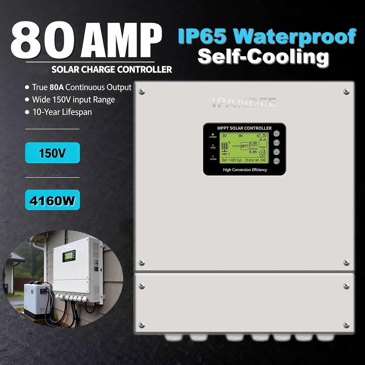
Image 2: Key Features Overview. This image visually summarizes the main features of the controller, including its 80A continuous output, IP65 waterproof rating, self-cooling design, 150V maximum input, and 4160W power capacity.

Image 3: Battery Compatibility. The image displays the controller's compatibility with a wide range of 12V/24V/36V/48V battery types, including LiFePO4, Sealed Lead-Acid (SLA), GEL, Flooded (FLD), and AGM batteries.
4. Installation
Follow these steps for proper installation of the solar charge controller:
- Prepare the Mounting Location: Ensure the mounting surface is sturdy and can support the weight of the controller. The IP65 rating allows for outdoor installation.
- Attach Hanging Boards: Secure the two hanging boards to the sides of the controller using the provided screws. Ensure they are firmly attached.
- Mark Drilling Points: Hold the controller with the attached hanging boards against the desired wall or surface. Mark the positions for the screw holes through the keyholes on the hanging boards.
- Drill Holes: Use a drill to create holes at the marked positions. Insert the green wall plugs into the drilled holes.
- Mount the Controller: Align the controller's hanging boards with the wall plugs. Insert screws into the top three holes on one side and tighten them one by one. Repeat for the other side.
- Secure Remaining Screws: Temporarily remove the controller to drill the remaining four screw holes. Insert wall plugs. Re-hang the controller and tighten all remaining screws with a screwdriver to ensure it is securely mounted.
Video 2: Installation Process. This video demonstrates the step-by-step process of mounting the solar charge controller to a wall, including attaching hanging boards, drilling holes, and securing the unit.
5. Wiring Instructions
Proper wiring is crucial for the safe and efficient operation of your solar charge controller. Follow these steps carefully:
- Prepare for Wiring: Ensure all power sources (solar panels and battery) are disconnected before starting any wiring.
- Remove Waterproof Cover: Use the provided Allen wrench to remove the screws securing the waterproof cover at the bottom of the controller. Carefully detach the cover to access the wiring terminals.
- Connect Solar Cable (PV): Through the PV waterproof interface, connect the solar panel cables (PV+ and PV-) to the corresponding terminals inside the controller. Ensure a secure connection.
- Connect Battery Cable (BAT): Through the BAT waterproof interface, connect the battery cables (BAT+ and BAT-) to the corresponding terminals. Ensure correct polarity and a tight connection.
- Connect Load DC Output (LOAD): If using a DC load, connect the load cables (LOAD+ and LOAD-) through the LOAD waterproof interface to the respective terminals.
- Connect RS485 Interface: The RS485 interface allows connection of a WiFi/Bluetooth module (optional) or a temperature sensing line. Connect the appropriate cable through the RS485 waterproof interface to its terminal.
- Secure Waterproof Cover: Once all connections are made and verified, replace the waterproof cover. Tighten the inner hexagon screws diagonally first, then secure all remaining screws to ensure a watertight seal.
- Power On Sequence:
- First, connect the battery MCB (Miniature Circuit Breaker).
- Then, turn on the PV MCB.
Video 3: Wiring Process. This video illustrates the detailed steps for wiring the solar charge controller, including removing the waterproof cover, connecting solar panels, battery, DC load, and RS485 module, and then re-securing the cover.
6. Operating Instructions and Interface Introduction
The controller features an intuitive display and buttons for monitoring and configuration:
- CHARGE Indicator (Blue): Indicates the controller is actively charging the battery.
- LOAD Indicator (Green): Indicates the DC load is in an open state (active).
- ALARM Indicator (Red): Indicates the controller is in standby mode or a fault has occurred.
Display Information:
- PV Voltage: Displays the current voltage from the solar panels.
- Charging Power: Shows the current power being delivered to the battery.
- Battery Voltage: Displays the current battery voltage.
- Device ID (Addr): Unique identifier for the controller.
- Charge Current: Shows the current flowing into the battery.
- Load Current: Displays the current drawn by the DC load.
- System Voltage/Battery Voltage (Bat Sys): Indicates the nominal system voltage.
- State: Shows the current operating state (e.g., CF Mode for charging).
- Bat Temp: Battery temperature.
- HS Temp: Controller internal temperature.
- Chg Curr: Recharging current.
- Chg Powr: Charging power.
- Chg Volt: Charging voltage.
- Load: DC Load Control status display.
- TOTAL: Total power generation.
- Firmware: Software version.
- Bat: Battery type display.
Button Functions:
- ESC: Exit or return to the previous menu level.
- ENTER: Enter a menu or confirm a selection.
- UP: Page up or increase a numerical value.
- DOWN: Page down or decrease a numerical value.
Video 4: Interface and Button Introduction. This video provides a visual guide to the controller's display interface, explaining the meaning of various parameters like PV voltage, charging power, battery voltage, and load current. It also demonstrates the function of each button (ESC, ENTER, UP, DOWN) for navigation and settings adjustment.
7. Settings
To access and modify settings, navigate through the main menu using the UP/DOWN buttons and confirm with ENTER.
Main Menu Options:
- Work Status: Displays current operating parameters and status.
- Normal Mode: Indicates normal operation.
- Fault: Displays fault status (e.g., No Fault).
- CV Charging: Constant Voltage Charging.
- PV Volt: Solar panel input voltage.
- Bat Temp: Battery temperature.
- HS Temp: Controller internal temperature.
- Load Curr: Load current.
- Chg Curr: Recharging current.
- Chg Powr: Charging power.
- Chg Volt: Charging voltage.
- Setting: Allows adjustment of various parameters.
- Load Set: Configure load control settings.
- Load: On/Off mode.
- BatLoadOff: Low voltage protection setting.
- BatLoadOn: Low pressure recovery setting.
- Load: Dual time control mode (am/pm On/Off times).
- Load: Closed X hours after dark (FT1-LigCtr-XX).
- PV Load On: Turn on load when PV voltage is lower than a set value (e.g., 30.1V).
- Ctr2: Open X hours before dawn (currently not set).
- PV LoadOff: Turn off load when PV voltage is higher than a set value (e.g., 50.0V).
- Time & Addr Set: Configure time and device ID.
- Time: Time setting.
- Date: Date setting.
- Addr: Device number setting.
- Bat Set: Configure battery parameters.
- Type: Battery Type (GEL, SEL, Li-ion, FLD, USER).
- Battery voltage: Auto recognition.
- Bulk Volt: Constant voltage charging voltage setting.
- Float Volt: Float charging voltage setting.
- MaxChgCurr: Maximum charging current setting (e.g., 100A).
- Full Volt: Full voltage setting (for Li-ion).
- NormalVolt: Normal voltage setting (for Li-ion).
- Over Volt: Overvoltage protection.
- (Recovery): Overvoltage recovery.
- CutoffVolt: Low voltage protection.
- (Recovery): Low pressure recovery.
- Load Set: Configure load control settings.
- Information: Displays device information.
- MPPT CHARGER: MPPT charger type.
- Charging voltage/charging current (e.g., 12/24/36/48V 100A).
- Battery type: (e.g., Lithium battery).
- Load: DC Load Control status display.
- TOTAL: Total power generation.
- Firmware: Software version (e.g., 4.1).
- Bat: Battery type display (e.g., Li-ion).
Video 5: Controller Settings and Menu Navigation. This video demonstrates how to navigate the controller's menu to check working status, adjust load settings, set time and device ID, and configure battery parameters for different battery types and protection thresholds.
8. Remote Monitoring (Optional Bluetooth Module)
The controller supports remote monitoring via a Bluetooth module (BT-02, sold separately) and a dedicated mobile application. This allows you to track real-time statistics, adjust settings, and receive alerts from your smartphone.
Bluetooth Module (BT-02) Overview:
- Power Light (Green): A constant light indicates the controller is connected.
- Signal Light (Blue):
- Blinking: Waiting for connection.
- Always off: Successful connection.
- Irregularly fast flashing: Data is being transmitted.
- Setup Button: Long press for 6 seconds to restore factory settings.
- Reset Button: Restarts the Bluetooth module.
Connecting via Bluetooth:
- Ensure the Bluetooth module is connected to the controller's RS485 port.
- Download the ipandee monitoring app from your device's app store (Apple or Google Play). QR codes for download are typically provided with the module.
- Open the app and select "Bluetooth Monitor".
- The app will search for available Bluetooth modules. Select your BT-02 module from the list.
- Once connected, the signal light on the BT-02 module will turn off, and you can access real-time data and settings through the app.

Image 4: Wireless Monitoring Setup. This image illustrates the connection between the solar charge controller, the BT-02 Bluetooth module, and a smartphone running the monitoring application, enabling wireless control and data access.
9. Specifications
| Feature | Detail |
|---|---|
| Item Weight | 16 Kilograms (35.2 pounds) |
| Manufacturer | IPANDEE |
| Product Dimensions | 16.9"L x 13.7"W x 5.3"H (42.9 x 34.8 x 13.5 cm) |
| ASIN | B0GKMBZGD5 |
| Item Model Number | MPPT solar charge controller ip65 |
| Color | White |
| Brand | ipandee |
| Voltage | 48 Volts (Auto 12V/24V/36V/48V) |
| Material | Metal |
| Max PV Input Voltage | 150V |
| Efficiency | 99.5% MPPT Efficiency |
| Protection Rating | IP65 (Dust-tight and protected against water jets from any direction) |
| Operating Temperature | -20°C to +50°C |
| Storage Temperature | -40°C to +70°C |
| Maximum Operating Altitude | 0 - 3,000 meters above sea level |

Image 5: Environmental Specifications. This image highlights the environmental operating conditions and protection ratings of the controller, including its operating temperature range, storage temperature, IP65 ingress protection, and maximum operating altitude.
10. Troubleshooting
This section provides guidance for common issues you might encounter. For more complex problems, please contact customer support.
- No Power/Display Off:
- Check battery connections and ensure they are secure and correctly polarized.
- Verify the battery voltage is within the operating range of the controller.
- Ensure the battery MCB is switched on.
- No Charging:
- Check solar panel connections and ensure they are secure and correctly polarized.
- Verify solar panel voltage (PV voltage) is within the controller's input range (150V Max).
- Ensure the PV MCB is switched on.
- Check for sufficient sunlight on the solar panels.
- Confirm battery type settings in the controller match your battery.
- Alarm Light On:
- Check the display for specific fault codes or messages.
- Review battery voltage for over-voltage or under-voltage conditions.
- Check for over-current conditions on the load or charging circuits.
- Ensure proper ventilation to prevent overheating.
- Load Not Working:
- Verify load connections are secure and correctly polarized.
- Check load settings in the controller (e.g., On/Off mode, time control, voltage thresholds).
- Ensure the battery has sufficient charge to power the load.
- Bluetooth Connection Issues:
- Ensure the BT-02 module is correctly connected to the controller.
- Check the BT-02 module's signal light (blinking means waiting for connection).
- Restart the Bluetooth module using the reset button.
- Ensure Bluetooth is enabled on your smartphone and the app has necessary permissions.
- Try restoring factory settings on the BT-02 module if issues persist.
11. Warranty and Support
The ipandee 80A MPPT Solar Charge Controller comes with a 1-Year Warranty from the date of purchase. This warranty covers defects in materials and workmanship under normal use.
For technical support, warranty claims, or any questions regarding your product, please contact ipandee customer service through the retailer where you purchased the product or visit the official ipandee store on Amazon: ipandee Store.
You can also find additional support and information via the mobile application's "Contact us" section, typically found under "General" settings, which may provide an email address like mygreenservice@hotmail.com.