256SL

Generic CADDXFPV 256SL Thermal Imaging Camera Instruction Manual

Model: 256SL

1. Introduction

This manual provides essential information for the safe and effective use of your Generic CADDXFPV 256SL Thermal Imaging Camera. Please read this manual thoroughly before operating the device and retain it for future reference. This camera is designed to provide thermal visualization for various applications, including drone integration, equipment inspection, and nighttime observation.

2. Safety Information

  • General Handling: Handle the camera with care. Avoid dropping or subjecting it to strong impacts.
  • Environmental Conditions: Do not expose the camera to extreme temperatures, high humidity, or corrosive environments. Operate within specified temperature ranges.
  • Power Supply: Ensure the power supply voltage and current match the camera's requirements. Incorrect power can damage the device.
  • Wiring: Verify all connections are secure and correctly wired before applying power. Incorrect wiring can lead to malfunction or damage.
  • Disassembly: Do not attempt to disassemble or modify the camera. This will void the warranty and may cause damage or injury.

3. Package Contents

Please check the package contents upon receipt. If any items are missing or damaged, contact your vendor immediately.

  • CADDXFPV 256SL Thermal Imaging Camera Unit
  • Connection Cable(s)
  • Instruction Manual (this document)

4. Product Overview

The CADDXFPV 256SL Thermal Imaging Camera is a compact and lightweight device designed for integration into various systems, particularly drones. It provides clear thermal visualization with support for high-resolution imaging formats, capturing heat signatures and contrasts in diverse environments. Its durable construction ensures reliable performance in various scenarios.

CADDXFPV 256SL Thermal Imaging Camera main unit and sensor module connected by a cable.

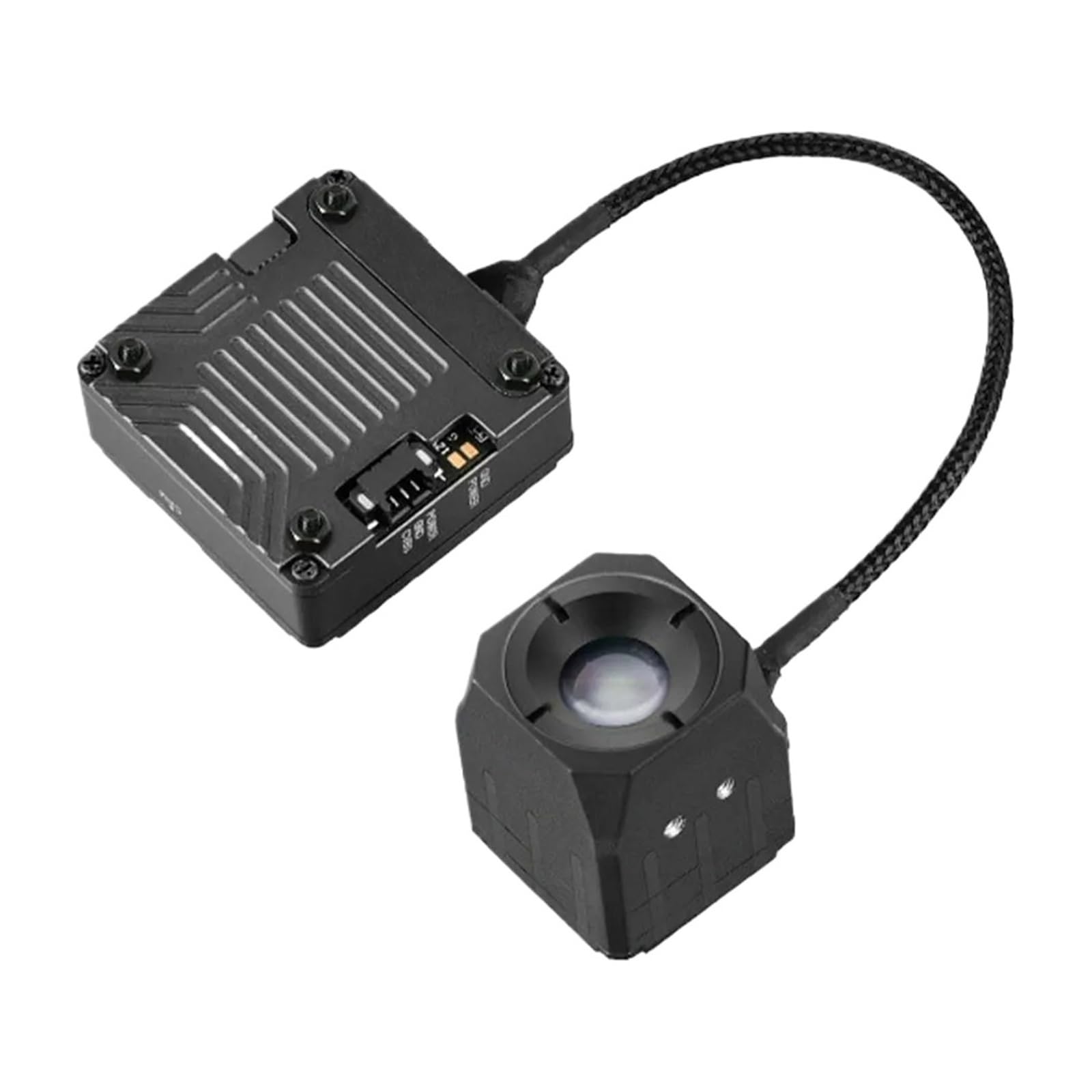
Figure 4.1: CADDXFPV 256SL Thermal Imaging Camera. The image shows the main processing unit connected to the thermal sensor module via a flexible cable.

The camera features user-friendly standardized interfaces for straightforward linking and quick deployment.

5. Setup

Follow these steps to set up your CADDXFPV 256SL Thermal Imaging Camera:

  1. Identify Components: Unpack all components and identify the main camera unit, the thermal sensor, and the connection cables.
  2. Mounting: Securely mount the camera unit and thermal sensor to your desired platform (e.g., drone). Ensure proper ventilation for the main unit.
  3. Connect Cables: Connect the thermal sensor to the main camera unit using the provided cable. Refer to the connection diagram below for proper wiring of power and video output.
  4. Power Connection: Connect the power input to a stable power source that meets the camera's voltage requirements. Observe polarity (GND, POWER).
  5. Video Output: Connect the CVBS (Composite Video Blanking and Sync) output to your display or recording device for PAL video signal.
Diagram showing connection points for USB, GND, POWER, and CVBS on the camera unit, and thermal/digital inputs on the sensor module.

Figure 5.1: Connection Diagram. This diagram illustrates the various input/output ports on the camera's main unit and the sensor module, including power, ground, video output, and thermal/digital connections.

6. Operating Instructions

Once the camera is properly set up and powered on, it will begin to output a PAL video signal. The camera is designed for continuous operation within its specified environmental limits.

  • Power On: Apply power to the camera. The device will typically start up and begin thermal imaging automatically.
  • Video Output: The thermal image will be displayed on the connected monitor or recording device via the CVBS output.
  • Observation: Use the thermal feed for various applications such as identifying heat sources, observing in low-light conditions, or inspecting equipment for temperature anomalies.
  • Integration: When integrated with a drone, ensure stable mounting and proper cable management to avoid interference or damage during flight.

7. Maintenance

Proper maintenance ensures the longevity and optimal performance of your thermal imaging camera.

  • Cleaning: Gently clean the lens of the thermal sensor with a soft, lint-free cloth. Avoid abrasive materials or harsh chemicals. For the main unit, use a dry cloth to wipe dust.
  • Storage: When not in use, store the camera in a cool, dry place, away from direct sunlight and extreme temperatures.
  • Cable Inspection: Periodically inspect all cables for signs of wear, cuts, or damage. Replace damaged cables immediately.

8. Troubleshooting

If you encounter issues with your camera, refer to the following common problems and solutions:

Problem Possible Cause Solution
No image on display No power; incorrect video connection; faulty cable. Check power supply and connections. Ensure video output is connected to the correct input on your display. Test with a different cable if available.
Image is distorted or flickering Loose cable connection; power fluctuations; electromagnetic interference. Secure all connections. Ensure stable power supply. Move camera away from strong electromagnetic fields.
Camera not powering on No power; incorrect voltage; faulty power cable. Verify power source is active. Check power cable for damage. Ensure power supply meets specifications.

If the problem persists after attempting these solutions, please contact your vendor for further assistance.

9. Specifications

The following table outlines the technical specifications for the CADDXFPV 256SL Thermal Imaging Camera:

Feature Specification
Model Number SDDEZZSIC-F718499C
Color Variant 256
Output Format PAL Output
Item Weight 1.76 ounces (approx. 50g)
Package Dimensions 4.72 x 1.57 x 1.18 inches
Material Composite Material
Technical drawing showing the dimensions of the camera unit and sensor module in millimeters.

Figure 9.1: Product Dimensions. This diagram provides detailed measurements of both the main camera unit and the thermal sensor module.

10. Warranty and Support

For warranty information and technical support, please refer to the documentation provided at the time of purchase or contact your authorized reseller or the manufacturer directly. Keep your purchase receipt as proof of purchase.

Documents - 256SL – 256SL
[pdf] Document
Maffeis Monica TERMINI CONDIZIONI DELL INIZIATIVA MEDIAWORLD 6 dic 2023 — Tutti gli smartphone Apple IPhone 15 15plus Pro Max MBPRO 14 M3 MAX 1SL PC ALL IN ONE 187676 IMAC 8CPU 10GPU 256BL TC NoIva FORLI MW CLUBdef assets ctfassets net hzxov1nxpus5 2srtiUczBZblfHai5NFgS4 7b9500a1a31372568ffaa00bd2da74e9 |||
9 TERMINI CONDIZIONI DELL INIZIATIVA MEDIAWORLD NO IVA FORLI MEDIAWORLD CLUB MEDIAMARKET S.p.A. ... 14 M3 MAX 14-1BK MBPRO 14 M3 MAX 14-1SL 187676 IMAC M3 8CPU-10GPU 256BL 187652 IMAC M3 8CPU-8GPU 256SL 187656 IMAC M3 8CPU-8GPU 256BL 187654 IMAC M3 8CPU-8GPU 256GN 187665 IMAC M3 8CPU-10GPU 256...
score:23 filesize: 317.54 K page_count: 5 document date: 2023-11-19
[pdf] Specifications Datasheet Catalog
DATASHEET SEARCH SITE IC COM CHIP SEMICONDUCTOR TRANSISTOR ELECTRONIC COMPONENT ISO ALLDATASHEET DATABOOK CATALOG ARCHIVE ICPD FCOM Provided By FREE DOWNLOAD Open as QUARTZCOM TX5 000345129 key 7cc796d61ffe23d5e3a48b7ddfbabded r 1 s1 dtsheet store data |||
TX5-256SL SMD TCXO Sine wave Features Parameter Frequency range Standard frequencies Frequency stability: vs. temperature vs. supply load change vs. aging Frequency tolerance ex. factory Supply voltage Supply current Output signal Output level Output load Frequency adjustment Phase noise 20.0 MH...
score:23 filesize: 178.22 K page_count: 1 document date: 2014-01-05
[pdf] Document
QT256cineshow cdr Allen Kool quantum5x qt256sl trewaudio |||
QUANTUM5X SYSTEMS INC. QT-256SL MINI BROADCAST VOICE TRANSMITTER The world s smallest belt-pack transmitter THE SYSTEM OF CHOICE FOR THE PROFESSIONAL Presenting the QT-256 Professional Mini Broadcast Belt-Pack Transmitter. This proprietary micro transmitter technology is so small you can hide it any...
score:23 filesize: 178.95 K page_count: 1 document date: 2006-01-25
[pdf] User Manual Instructions Decleration of Conformity Warranty Accessories
AP600 AP600R Zubler USA 9 SL230 Best Nr Control panel compact 822 0641 for integration 0642 Power adapter C14 CEE 012 00701 SL AP control wire 10m 825 25644 ap600 ap600r automatic port opener user manual zublerusa 2020 10 |||
AP600 / AP600R Automatic Port opener EN a02-2019 www.zubler.de 2 Content 0. User information ... -256-17 SL-AP-R 2,5m 825-25640 special wires SL24 page 17 825-256xx Relay adapter SL 230V 825-256SL Pressure reducer DM 06 822-06xx 9 1.2 Assembly of the automatic port opener Fig. 6 11 12...
score:22 filesize: 3.37 M page_count: 28 document date: 2019-03-29
[pdf] User Manual Instructions Decleration of Conformity Warranty Accessories
m Z1 deenfr 200804 indd ECO CAM Zubler USA 4 0 We Gerätebau GmbH Buchbrunnenweg 26 89081 Ulm Jungingen declare that the product vacuuming unit conforms to health and safety 6 1 Item Number Adaptor C14 CEE 012 00702 H14 Filter H Typ 556 0052 Activated carbon filter C 0051 exhaust adapter RD72 DN75 896 1103 diffusor holder without 0057 manual z1eco z1cam zublerusa 2020 10 |||
Z1 ECO Z1 CAM Single suction systems Z1 EN 02-2020 www.zubler.de Content 0. User information p ... chine for the extraction, you need a special cable from the list on page 10. Fig. 9 Order no. 825-256SL SL230 Ssepeecpiaagl eca1b0le SL-24, Relais Maschine 230V Maschine 24V Maschine 11 Interfac...
score:19 filesize: 6.55 M page_count: 36 document date: 2020-08-04
[pdf] Guide Borchure
Single station suction systems Zubler USA THE DEVICE WITH FILTER BAG The types Z1 ECO and CAM are suitable for a wide range of applications due to their large filter bags Their volume 11 litres is unique in the dental field single units In addition z1eco z1cam series brochure zublerusa 2020 10 |||
SUCTION SYSTEMS Single station suction systems Z1 ECO with filter bag for work stations and dust- ... D-SUB 9-pole for imes-icore Item No.: 825/25616 230 Volt interface C14 for Zirkonzahn Item No.: 825/256SL Technical specification: Dimensions w x h x d : Weight: Voltage: Nominal power ECO/CAM :...
score:18 filesize: 1.4 M page_count: 12 document date: 2020-05-28
[pdf] Document
Layout 1 Discontinued Zubler Suction USA B V7000 de A5 140314 zublerusa 2022 10 |||
V7000 Absauganlage / Kollektorlose Saugturbine de BEDIENUNGSANLEITUNG 03-2014 www.zubler.de Inh ... , Gerte bis 500W AP501 Saugstellenffner Bestellnummer 825/25601 825/25600 825/25602 825/25646 825/256SL 825/2566 825/2566U5 825/2566U10 825/256K 825/25648 825/256 825/25643 825/25644 822/050 Seite ...
score:16 filesize: 892.08 K page_count: 23 document date: 2014-03-14
[pdf] Document
5 Maffeis Monica MediaMarket S p A TERMINI CONDIZIONI DELL INIZIATIVA MEDIAWORLD 1 day ago — 234139 HEADPHONE 2 0 INTER 163436 PS5 PULSE 3D WLESS BLK 137811 MICR 180651 CAMO Page 6 121731 MILAN TC APP DAYS MW CLUB 25 26 DICEMBRE assets ctfassets net hzxov1nxpus5 66LiuZv523FAyO0C4KszPG 320658b0d6e88cf18b9d2231a3b9d6f4 |||
9 TERMINI CONDIZIONI DELL INIZIATIVA MEDIAWORLD -15 IN APP CON MW CLUB 25-26 DICEMBRE MEDIAMARK ... ROSA IMAC M3 8CPU-10GPU 256BL IMAC M3 8CPU-10GPU 256GN IMAC M3 8CPU-10GPU 256PK IMAC M3 8CPU-10GPU 256SL IMAC M3 8CPU-10GPU 512BL 172570 172564 172568 172562 405272 172563 213138 213143 213136 2131...
score:14 filesize: 569.7 K page_count: 16 document date: 2024-12-20
[pdf] Document
647958de kva Bedienungsanleitung Kühl Gefrierkombination Einbau ASKO PREMIUM FORS AG eeddec764aaa26598f3e2e10fd2d0116dc27a070 RFN31831EI Gebrauchsanweisung de fors ch content imported |||
012314546784913 546 0 456789 # * ,- , ...#///0:: 122 632 3;/3334 ... 5 -: 9 9-6 E.: ; O 6 -06 - 4 ;57 AAA1; -.=. 62 9 .:-N:=26 P :66 . L66 2 5.20-256SL.--29 ;;;:- 4 58 /-0=6/; 69 :C: 1F 3 8 6.46 D-5 - F 7; 0 4 --:AK 2 5;; 98 -79 . 9L ...
score:12 filesize: 920.6 K page_count: 36 document date: 2024-02-09
[pdf] User Manual Instructions Guide
q Automotive Diagnostic Fault Codes Manual cloud politala ac id Jurusan Mesin Otomotif Materi Kuliah Teknologi ECU Praktikum
AUTOMOTIVE -*q . 4 DIAGNbS.l A ;FAULT cooesL I-h 4 P I. I Wh4 ET I I ,,12 Extracting, interpreting and clearing of fault codes Fault code tables and step-by-step instructions The guide that shows you how and saves you money Automotive Diagnostic Fault Codes Techbook Charles White S...
score:11 filesize: 16.13 M page_count: 221 document date: 2005-12-07