1. Introduction
This instruction manual provides essential information for the safe and efficient installation, operation, and maintenance of your DATOUBOSS 64.32kWh 48V 314Ah LiFePO4 Lithium Battery Bank. Please read this manual thoroughly before using the product and retain it for future reference. This battery system is designed for high-capacity energy storage in industrial, home solar, RV, and off-grid applications.
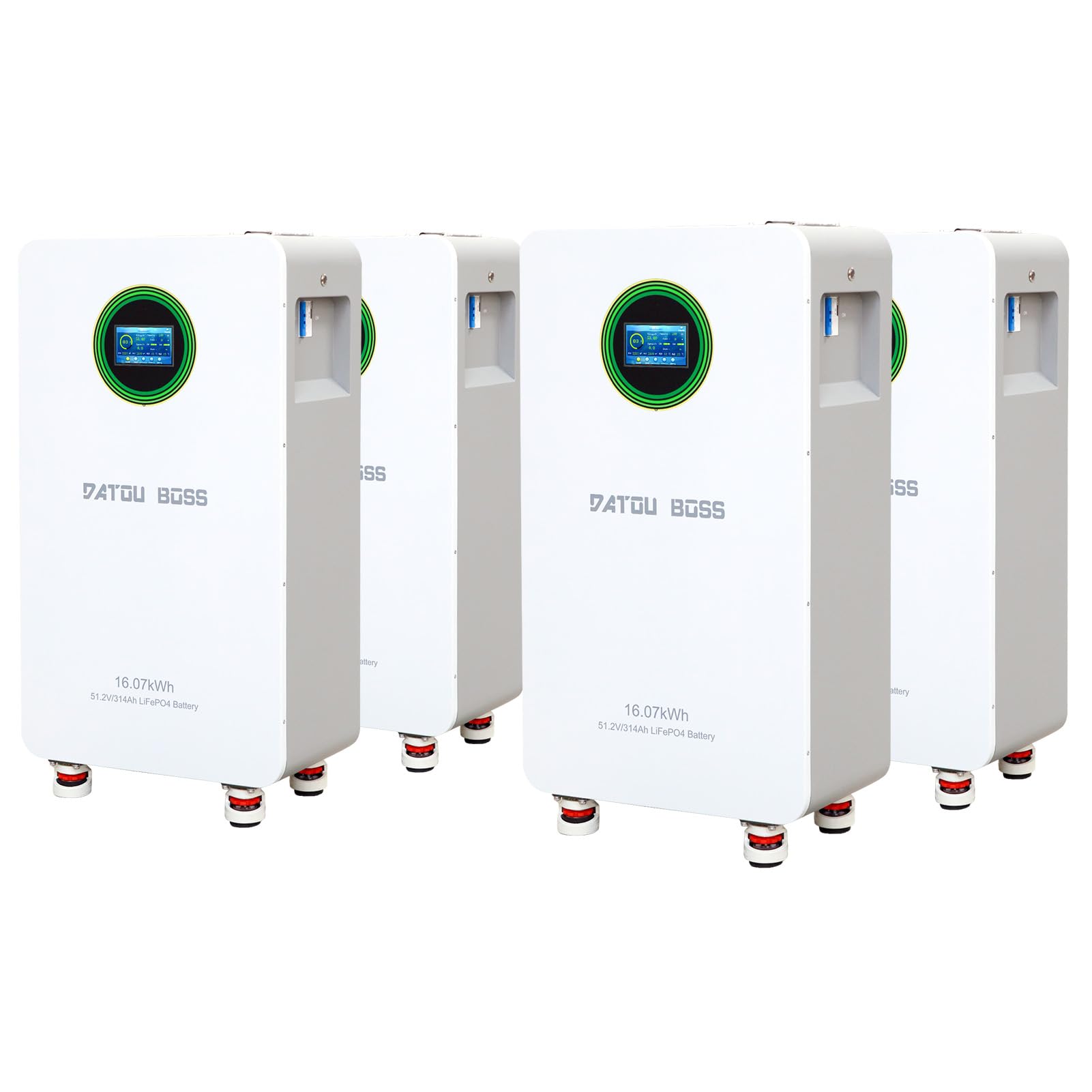
Figure 1: Overview of the DATOUBOSS 48V 314Ah LiFePO4 Lithium Battery Bank, showcasing its compact design.
2. Safety Guidelines
Adherence to the following safety guidelines is crucial to prevent injury, damage to the battery, and ensure optimal performance.
- Always disconnect power before installation or maintenance.
- Ensure proper ventilation around the battery bank.
- Do not expose the battery to fire, water, or extreme temperatures outside the specified operating range.
- Avoid short-circuiting the battery terminals.
- Only use compatible charging equipment and inverters.
- Installation should be performed by qualified personnel.
- Wear appropriate personal protective equipment (PPE) such as insulated gloves and eye protection during installation.

Figure 2: Diagram illustrating the multiple protection functions of the DATOUBOSS battery, including overvoltage, overcharge, overdischarge, temperature, and overcurrent protection.
3. Package Contents
Verify that all items listed below are present in your package:
- DATOUBOSS 48V 314Ah LiFePO4 Battery Pack (4 units for 64.32kWh system)
- Mounting Bracket
- Wall-Mount Brackets
- Positive Battery Connection Cable
- Negative Battery Connection Cable
- Communication Cable
- Screws
- Instruction Manual (this document)

Figure 3: Image displaying all items included in the DATOUBOSS battery package, such as the battery unit, mounting bracket, cables, and instruction manual.
4. Product Features and Components
4.1 Key Features
- High Capacity: Each 314Ah LiFePO4 battery unit provides significant energy storage, totaling 64.32 kWh for a 4-pack system.
- Smart BMS: Integrated 210A Smart Battery Management System for robust protection and optimized performance.
- Long Cycle Life: Designed for over 6000 deep cycles at 70% State of Health (SOH) at 25°C.
- Scalability: Supports parallel connection of up to 15 batteries for expanded energy storage.
- Communication Ports: Equipped with standard CAN and RS485 ports for seamless integration with compatible inverters.
- Color Touch Screen: For real-time monitoring and easy operation.
4.2 External Components
Familiarize yourself with the external components of the battery unit:

Figure 4: Detailed diagram labeling the external components of the DATOUBOSS battery, including the reset switch, indicators, DIP address, communication ports, battery terminals, push button switch, and air switch.
- Reset Switch: Used to reboot or shut down the unit.
- Switching Indicator: Displays the switch status.
- Operation Indicator: Shows operational status.
- Alarm Indicator: Alerts for system warnings.
- Battery Indicator: Displays remaining capacity.
- Battery Positive/Negative Terminals: For power connections.
- DIP Address Switches: For setting addresses in parallel configurations.
- RS485, CAN, RS232 Ports: For external and parallel communication.
- Dry Contact: Normally open or normally closed signal drive relay.
- Push Button Switch: Controls power on/off.
- Air Switch: Disconnects input and output for safety.
- LCD Touchscreen: For monitoring and configuration.
5. Installation
5.1 Site Selection and Preparation
- Do not install the battery pack on flammable building materials.
- Install the battery box at eye level for easy LCD display readability.
- Maintain an ambient temperature between 0°C and 55°C for optimal operation.
- Install vertically on a wall.
- Ensure sufficient heat dissipation space and wiring removal space (at least 20cm/7.8in on sides and 50cm/19.6in above/below).
5.2 Mounting Steps

Figure 5: Illustration demonstrating the recommended installation method for the DATOUBOSS battery, including wall mounting steps and clearance requirements.
- First, fix the mounting bracket to the wall using expansion screws.
- Next, fix the bracket to the back shell of the battery unit with short screws.
- Finally, hang the battery unit onto the wall bracket.
Note: This installation method is only suitable for concrete or other non-flammable surfaces.
5.3 Parallel Wiring and DIP Switch Configuration
When connecting multiple battery units in parallel, proper DIP switch configuration is essential for communication and address assignment.

Figure 6: Diagram explaining the DIP switch settings for addressing multiple DATOUBOSS battery units in a parallel configuration, along with a table of address assignments.
When connecting battery packs in parallel, use the DIP addressing function. If DIP6 is connected to ON, the system will use automatic address assignment. Otherwise, use the default automatic addressing function. The DIP switches on the BMS are used to set the address to distinguish different data packets.
Refer to the table in Figure 6 for specific DIP switch settings for each battery unit (PACK1 to PACK15).
6. Operation
6.1 Powering On/Off
- To power on, ensure all connections are secure, then activate the external air switch and press the internal push button switch.
- To power off, reverse the process: press the internal push button switch, then deactivate the external air switch.
6.2 Monitoring via Touch Screen
The integrated color touch screen provides real-time monitoring of battery status and parameters.
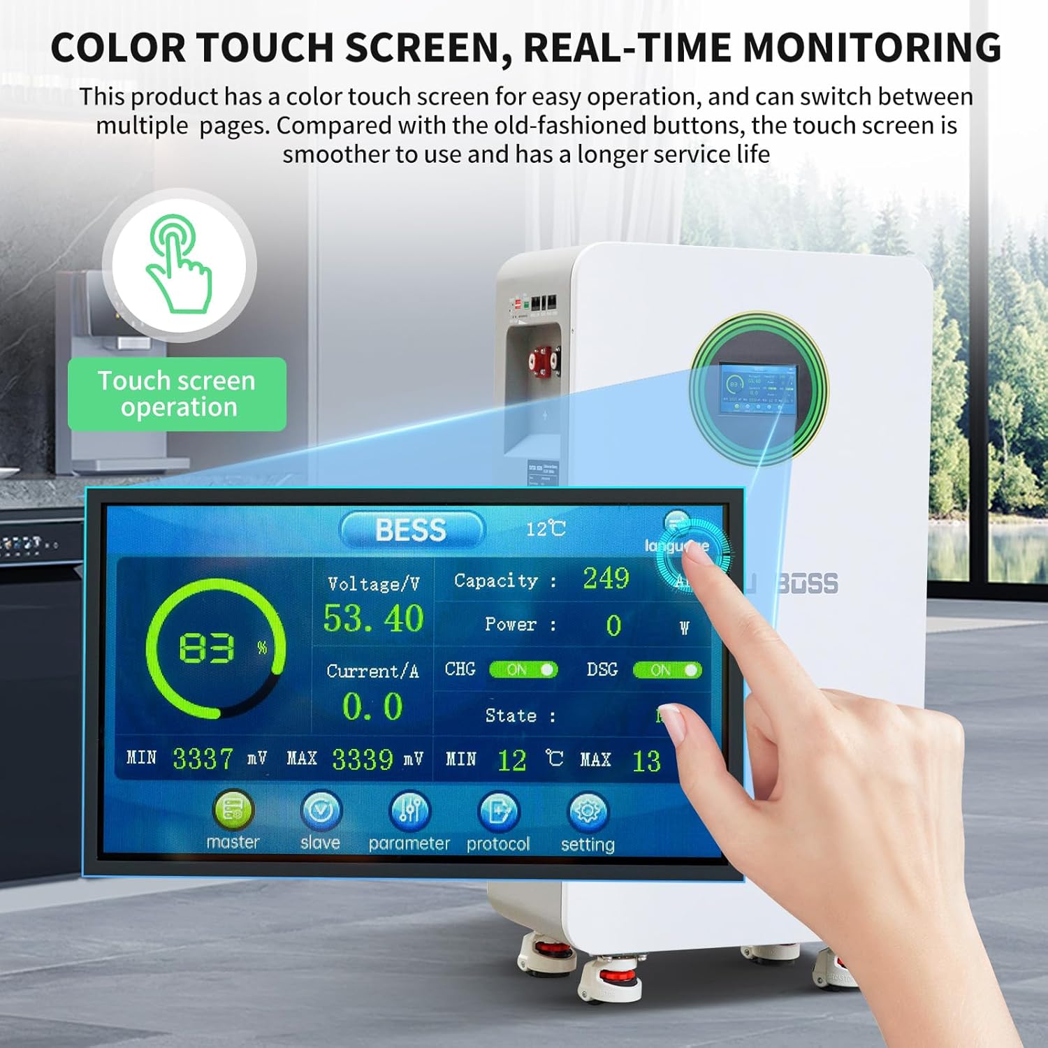
Figure 7: Image showing the color touch screen interface of the DATOUBOSS battery, displaying real-time monitoring data such as voltage, capacity, current, and state.
- The screen displays voltage, current, capacity percentage, power, and charge/discharge status.
- Navigate through different pages to view detailed parameters, master/slave unit status, and communication protocols.
6.3 Communication with Inverters
The battery supports RS485 and CAN communication protocols for integration with compatible inverters. Ensure the correct communication cables are connected and the inverter settings match the battery's protocol.

Figure 8: Close-up view of the RS485, CAN, and RS232 communication ports on the DATOUBOSS battery, compatible with various inverters.
7. Maintenance
Regular maintenance ensures the longevity and optimal performance of your battery bank.
- Periodically inspect all cable connections for tightness and corrosion.
- Keep the battery unit clean and free from dust and debris.
- Monitor the battery's performance via the touch screen or connected inverter.
- Ensure adequate ventilation around the battery to prevent overheating.
- Avoid prolonged storage in a fully discharged state.
8. Troubleshooting
The DATOUBOSS battery is equipped with a Smart BMS that provides multiple protection functions. If an issue occurs, check the alarm indicator and the touch screen for error messages.
| Issue | Possible Cause | Resolution |
|---|---|---|
| Battery not charging | Overcharge protection activated (54.0V) or charge low temperature protection (0°C). | Check charging voltage and ambient temperature. Allow battery to warm up if too cold. |
| Battery not discharging | Overdischarge protection activated (43.2V) or discharge low temperature protection (-15°C). | Recharge the battery. Allow battery to warm up if too cold. |
| System shuts down unexpectedly | Overcurrent protection (215A) or high temperature protection (50°C charge, 45°C discharge). | Reduce load. Ensure proper ventilation. Allow battery to cool down. |
| Short circuit detected | External short circuit. | Identify and clear the short circuit. The system has a recovery method of 'Remove load and charge release'. |
| Communication error | Incorrect cable connection or protocol settings. | Verify communication cable integrity and ensure DIP switch settings match the inverter protocol. |
9. Technical Specifications
The following table outlines the key technical parameters of the DATOUBOSS 48V 314Ah LiFePO4 Lithium Battery.

Figure 9: A table providing detailed technical parameters for the DATOUBOSS LFP48-314-FSD battery, covering electrical, thermal, and communication specifications.
| Parameter | Specification |
|---|---|
| Model | LFP48-314-FSD |
| Battery Capacity | 16.07 kWh (per unit) |
| Battery Internal Resistance | ≤ 10mΩ |
| Single Battery Capacity | 314Ah |
| Nominal Operating Voltage | 51.2V |
| Maximum Output Current | 210A |
| Standard Input Current | 150A (Maximum 210A) |
| Overpressure Protection | 58.4V |
| Overcharge Protection Recovery | 54.0V |
| Overdischarge Protection | 43.2V |
| Overdischarge Protection Recovery | 48V (tunable, within 30 seconds) |
| Charging Over-Temperature Protection | 50°C |
| Charge Over-Temperature Protection Recovery | 45°C (tunable) |
| Charging Low Temperature Protection | 0°C (tunable) |
| Charge Cryoprotection Recovery | 5°C |
| Discharge Over-Temperature Protection | 50°C |
| Discharge Over-Temperature Protection Recovery | 45°C |
| Low Temperature Protection | -15°C |
| Low Temperature Protection Recovery | -10°C |
| Charging Overcurrent | 215A |
| Discharge Overcurrent Protection | 215A |
| Short Circuit Protection | Recovery method: 'Charge Removal, Load Removal' |
| Amount Of Electricity Shipped | 40% to 60% |
| Equalization | Passive equilibrium |
| Power Off Self-Consumption | ≤ 300uA |
| Battery Cycle Life (25°C, 70% SOH) | ≥ 8000 cycles |
| Battery Cycle Life (45°C, 70% SOH) | ≥ 3000 cycles |
| Communication Protocols | RS232, RS485, CAN |
| Dimensions (L x W x H) | 453 x 260 x 879 mm |
| Weight | 110 kg |
10. Warranty and Support
For warranty information, technical support, or service inquiries, please refer to the warranty card included with your product or contact DATOUBOSS customer service directly. Ensure you have your product model number and purchase details available when contacting support.


