
Q37H4-AM2
Generic Q37H4-AM2 Motherboard User Manual
Model: Q37H4-AM2 for M6660G T850 Desktop Systems
1. Introduction
This manual provides detailed instructions for the installation, operation, and maintenance of the Generic Q37H4-AM2 Motherboard. Please read this manual thoroughly before proceeding with installation or use to ensure proper functionality and to prevent damage to the product or other components. Keep this manual for future reference.
2. Product Overview
The Generic Q37H4-AM2 Motherboard is designed for optimal performance and compatibility with various computing needs. It features a robust design for longevity and reliability, suitable for M6660G T850 desktop systems.

Figure 2.1: Top-down view of the Q37H4-AM2 motherboard, highlighting the CPU socket, RAM slots, and various expansion slots and connectors. This image provides a general layout of the board's components.
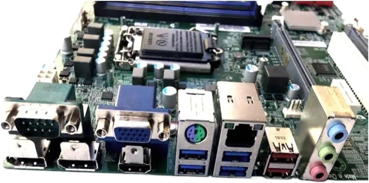
Figure 2.2: Rear I/O panel of the Q37H4-AM2 motherboard, displaying ports such as USB, VGA, HDMI, Ethernet, and audio jacks. This view is crucial for connecting external peripherals.

Figure 2.3: Close-up view of the Q37H4-AM2 motherboard, showing the model number label (Q37H4-AM2) and additional expansion slots. This image helps in identifying the specific model and available expansion options.
3. Setup and Installation
Before beginning installation, ensure your workspace is clean, well-lit, and static-free. It is recommended to wear an anti-static wrist strap.
3.1. Package Contents
Verify that all components are present in the package:
- Generic Q37H4-AM2 Motherboard
- I/O Shield
- SATA Cables (quantity may vary)
- User Manual (this document)
- Driver CD/USB (if included)
3.2. Installing the CPU
- Locate the CPU socket (LGA1151) on the motherboard.
- Gently lift the load lever and open the CPU socket cover.
- Align the CPU with the socket, ensuring the golden triangle on the CPU matches the triangle on the socket.
- Carefully place the CPU into the socket without forcing it.
- Close the socket cover and push down the load lever until it locks into place.
- Apply thermal paste to the CPU surface and install the CPU cooler.
3.3. Installing RAM
- Locate the DDR RAM slots on the motherboard.
- Open the clips at both ends of the RAM slot.
- Align the notch on the RAM module with the notch in the slot.
- Insert the RAM module firmly into the slot until the clips snap into place.
- Repeat for additional RAM modules, following dual-channel configuration guidelines if applicable.
3.4. Connecting Peripherals
- Power Supply: Connect the 24-pin ATX power connector and the 8-pin (or 4-pin) CPU power connector from your power supply to the motherboard.
- Storage Devices: Connect SATA data cables from your storage drives (HDD/SSD) to the SATA ports on the motherboard. Connect power cables from the power supply to the drives.
- Front Panel Connectors: Connect the power button, reset button, HDD LED, power LED, and front USB/audio headers to the corresponding pins on the motherboard. Refer to the motherboard diagram for exact pin locations.
- Expansion Cards: Insert graphics cards or other expansion cards into the appropriate PCIe slots.
4. Operating Instructions
4.1. First Boot
- After all components are installed and connected, ensure all cables are secure.
- Connect your monitor, keyboard, and mouse.
- Plug in the power cord to the power supply and turn on the power switch.
- Press the power button on your computer case.
- The system should boot and display the BIOS/UEFI screen.
4.2. BIOS/UEFI Configuration
To enter the BIOS/UEFI setup, press the designated key (usually DEL or F2) during the initial boot sequence. Here you can configure boot order, system time, and other hardware settings.
4.3. Operating System Installation
Insert your operating system installation media (USB drive or DVD) and configure the boot order in BIOS/UEFI to boot from it. Follow the on-screen instructions to install your preferred operating system.
4.4. Driver Installation
After installing the operating system, install the necessary drivers for the motherboard chipset, audio, network, and any other integrated components. These drivers are typically provided on a CD/USB or can be downloaded from the manufacturer's website.
5. Maintenance
Regular maintenance helps ensure the longevity and stable operation of your motherboard and system.
- Dust Removal: Periodically clean dust from the motherboard and other components using compressed air. Ensure the system is powered off and unplugged before cleaning.
- BIOS/UEFI Updates: Check the manufacturer's website for BIOS/UEFI updates. Updates can improve stability, compatibility, and performance. Follow update instructions carefully to avoid system damage.
- Driver Updates: Keep your drivers updated to ensure optimal performance and compatibility with new software and hardware.
- Cable Management: Ensure internal cables are neatly routed to improve airflow and prevent interference.
6. Troubleshooting
This section provides solutions to common issues you might encounter.
6.1. No Power / No Display
- Check all power connections: 24-pin ATX, 8-pin CPU, and power supply cable.
- Ensure the power supply switch is in the "ON" position.
- Verify that the monitor is connected and powered on.
- Reseat RAM modules and expansion cards.
- Try booting with minimal components (CPU, one RAM stick, graphics card if no integrated graphics).
6.2. System Instability / Crashes
- Check CPU and GPU temperatures. Overheating can cause instability.
- Ensure all drivers are correctly installed and up to date.
- Run memory diagnostic tools to check for faulty RAM.
- Verify power supply wattage is sufficient for all components.
- Check for loose connections or improperly seated components.
6.3. Peripheral Not Detected
- Ensure the peripheral is properly connected to the correct port.
- Check device manager in your operating system for driver issues.
- Try connecting the peripheral to a different port.
- Verify that the peripheral is powered on (if applicable).
7. Specifications
| Feature | Specification |
|---|---|
| Brand | Generic |
| Model | Q37H4-AM2 |
| CPU Socket | LGA1151 |
| Compatible Devices | Desktop PCs |
| RAM Memory Technology | DDR |
| Chipset Type | Q370 |
| Memory Clock Speed | 1 GHz |
| RAM Memory Maximum Size | 1 GB |
| Memory Slots Available | 2 |
Note: Some specifications provided in the source data appear to be generic placeholders and may not accurately reflect the specific model. Users should consult the official manufacturer's documentation for precise details. For example, 1 GHz memory speed and 1 GB maximum RAM are typically placeholder values for modern motherboards. The image shows 2 memory slots.
8. Warranty and Support
For warranty information, please refer to the documentation provided with your purchase or contact the seller directly. Technical support may be available through the seller or the original equipment manufacturer (OEM) if this is a replacement part for a specific system.
Seller: Er HHh Store
ASIN: B0GG437SW4
Ask a question about this manual
Ask about setup, troubleshooting, compatibility, parts, safety, or missing instructions. Manuals+ will review the question and use this page’s manual context to help answer it.