
1. Product Overview
The ipandee NS24H60 is a 60 Amp Maximum Power Point Tracking (MPPT) solar charge controller designed for efficient charging of 12V and 24V battery systems. It supports various battery types, including Sealed, Gel, Flooded lead-acid, and customizable lithium batteries. The controller features a 150V maximum PV input, ensuring compatibility with diverse solar array configurations. It delivers a continuous 60A output, supporting up to 840W for 12V systems and 1680W for 24V systems, and includes a built-in 30A DC load output.
This controller utilizes advanced MPPT technology to maximize solar energy harvest, even under varying light conditions. Its robust design ensures stable operation and a long lifespan.


2. Safety Information
Read all instructions and warnings in this manual before installation and operation. Failure to follow these instructions may result in electric shock, fire, or severe injury. Keep this manual for future reference.
2.1 General Safety Precautions
- Ensure all wiring is correctly polarized and securely connected.
- Install appropriate fuses or circuit breakers for both the solar panel array and the battery bank.
- Avoid installing the controller in direct sunlight, high temperatures, or humid environments.
- Ensure adequate ventilation around the controller for proper heat dissipation.
- Do not attempt to disassemble or repair the controller. Contact qualified personnel for service.
- Wear appropriate personal protective equipment (PPE) during installation, including insulated gloves and eye protection.
2.2 Protection Features
The NS24H60 controller incorporates multiple electronic safeguards to protect the system and ensure safe operation:
- PV Over Current Protection: Prevents damage from excessive current from the solar array.
- Battery Overvoltage Protection: Disconnects charging when battery voltage exceeds safe limits.
- Battery Discharge Protection: Prevents over-discharge of the battery.
- Low-Temp Charging Protection: Protects lithium batteries from charging at dangerously low temperatures.
- Over-Temperature Protection: Reduces power or shuts down if the controller's internal temperature becomes too high.
- Load Overload Protection: Disconnects the load output if current exceeds the rated limit.
- Short-Circuit Protection: Automatically disconnects in case of a short circuit.
- Reverse Polarity Protection: Protects against incorrect wiring of PV, battery, or load connections.


3. Product Components
3.1 Package Contents
The product package includes:
- 1 x ipandee NS24H60 MPPT Solar Charge Controller
- 1 x Comprehensive English User Manual (this document)
- Mounting hardware
3.2 Physical Description and Dimensions
The NS24H60 features an all-aluminum alloy housing for enhanced durability and efficient heat dissipation. It is designed with a compact form factor for various installation environments.
- Dimensions (L x W x H): 9.65" x 6.69" x 2.72" (245mm x 170mm x 69mm)
- Weight: 2.25 kg
- Material: Aluminum
- Display Type: OLED

4. Installation and Wiring
Proper installation is crucial for the safe and efficient operation of your solar charge controller. Follow these steps carefully.
4.1 Mounting the Controller
- Choose a dry, well-ventilated location away from direct sunlight and heat sources.
- Mount the controller vertically on a non-flammable surface to allow for optimal heat dissipation.
- Use the provided mounting hardware and preserved mounting holes or side mounting plates to secure the controller.
- Ensure there is sufficient clearance around the controller for air circulation.
4.2 Wiring Sequence
Connect the components in the following order to prevent damage to the controller or battery:
- Connect the Battery: Connect the battery to the controller's battery terminals. Ensure correct polarity (positive to positive, negative to negative). The controller will auto-detect the system voltage (12V or 24V).
- Connect the Solar Panels (PV Array): Connect the solar panel array to the controller's PV input terminals. Ensure correct polarity. Do not exceed the maximum PV input voltage of 150V.
- Connect the DC Load (Optional): Connect your DC loads to the controller's load output terminals. Ensure correct polarity.
Important: Always connect the battery first, then the solar panels, and finally the load. Disconnect in the reverse order: load, then solar panels, then battery.

4.3 Connecting the Temperature Sensor
Connect the included temperature sense cable to the designated port on the controller. This allows the controller to monitor battery temperature and adjust charging parameters for optimal battery health and lifespan.
5. Operation
Once installed, the controller will begin operation. The OLED display provides real-time system information.
5.1 System Voltage Auto-Detection
The NS24H60 automatically detects 12V or 24V battery systems upon initial connection. Ensure your battery bank voltage matches the system voltage.
5.2 Battery Type Selection and Activation
The controller is compatible with various battery types. You can select the appropriate battery type through the controller's interface to ensure optimal charging. Supported types include LiFePO4, Lithium, AGM, Gel, Flooded, Sealed Lead-Acid, and user-defined battery types.
The built-in Lithium Activation function can help recover lithium batteries that have entered a low-voltage shutdown state due to their Battery Management System (BMS), restoring their charging capability without requiring an external charger.

5.3 Charging Modes
The controller employs a multi-stage charging algorithm to optimize battery health and lifespan:
- Bulk Charge: Charges the battery at maximum current until voltage reaches the absorption level.
- Constant Charging (Absorption): Maintains a constant voltage while current gradually decreases.
- Float Charge: Reduces voltage to a lower level to maintain the battery at full charge.
- Equalization Charge (for Lead-Acid): Periodically overcharges the battery to balance cell voltages and prevent sulfation.
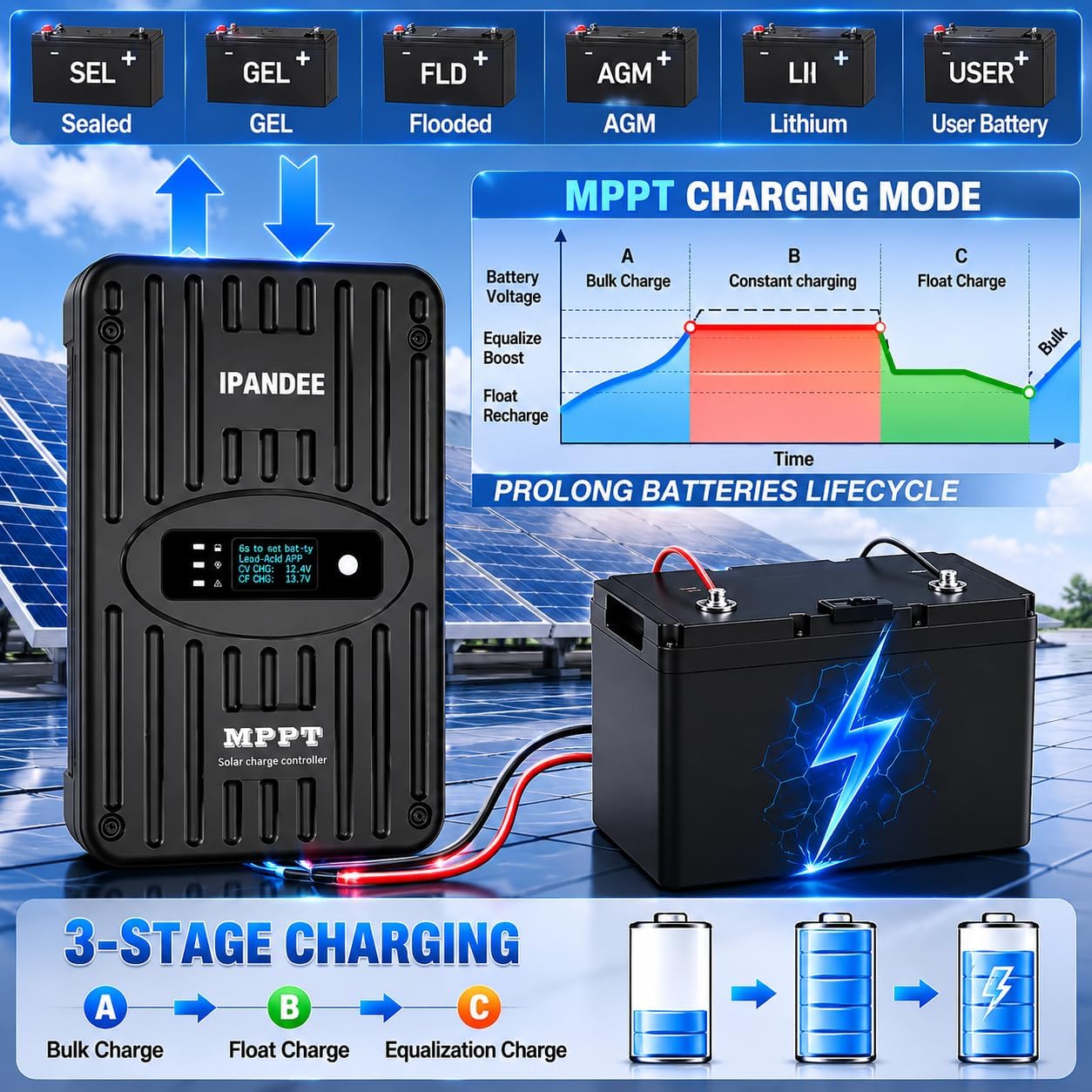

5.4 Monitoring via OLED Display
The integrated OLED display provides real-time data on your solar system's performance. Information typically includes:
- PV Voltage (PV Volt)
- Battery Voltage (Bat Volt)
- Charging Current (CHG Curr)
- Charging Power (CHG Power)

5.5 Optional Bluetooth Monitoring
For enhanced monitoring and control, an optional Bluetooth module (BT-02, sold separately) can be connected to the controller. This allows for wireless monitoring of your PV system and adjustment of settings via a compatible smartphone application (Solarmate App).

5.6 Load Output Modes
The integrated load controller operates at a rated 30A at battery voltage and offers three programmable modes:
- Normally Open/Closed: Configures the load output to be continuously on or off.
- Dual-Time: Allows setting two distinct time periods for the load to be active.
- Light Control with Timer Delay: Activates the load based on ambient light levels, with an adjustable timer.
6. Maintenance
Regular maintenance helps ensure the longevity and optimal performance of your solar charge controller.
- Periodic Inspection: Visually inspect the controller and all connections every few months. Check for any loose wires, corrosion, or signs of damage.
- Cleaning: Keep the controller clean and free from dust and debris. Use a dry, soft cloth to wipe the exterior. Do not use liquid cleaners or solvents.
- Ventilation: Ensure that the ventilation fins are not obstructed to allow for proper heat dissipation.
- Connection Checks: Periodically check the tightness of all terminal connections (battery, PV, load) to prevent resistance and overheating.
- Battery Health: Monitor your battery's health and voltage regularly. Follow the battery manufacturer's maintenance guidelines.
7. Troubleshooting
This section provides guidance for common issues. For problems not listed here, contact customer support.
| Problem | Possible Cause | Solution |
|---|---|---|
| No display/Controller not powering on | Battery not connected or low voltage; Reverse polarity; Blown fuse. | Check battery connections and voltage. Ensure correct polarity. Check battery fuse. |
| No charging from solar panels | PV array not connected; Low solar input; PV reverse polarity; PV overvoltage. | Check PV connections and polarity. Ensure sufficient sunlight. Verify PV voltage is within limits. |
| Load output not working | Load disconnected; Overload; Short circuit; Battery low voltage. | Check load connections. Reduce load. Check for short circuits. Ensure battery voltage is above low voltage disconnect setting. |
| Battery not fully charged | Incorrect battery type setting; Insufficient PV power; High battery internal resistance. | Verify battery type setting. Increase PV array size or check for shading. Inspect battery health. |
| Controller overheating | Poor ventilation; Excessive ambient temperature; Overload. | Ensure adequate airflow around the controller. Relocate to a cooler environment. Reduce load or PV input if consistently overloaded. |
8. Technical Specifications
The following table outlines the key technical specifications for the ipandee NS24H60 MPPT Solar Charge Controller.
| Parameter | Value |
|---|---|
| Model | NS24H60 |
| Rated Charge Current | 60A |
| Rated Load Current | 30A |
| Max. PV Input Voltage (Voc) | 150VDC |
| MPPT Efficiency | 99.5% |
| Heat Dissipation Method | All aluminum alloy shell self-heating |
| Settleable Lithium Battery System | 8VDC-30VDC |
| Min. Vmpp Voltage | Battery Voltage +2V |
| Start-up Charging Voltage | Battery Voltage +3V |
| Low Input Voltage Protection | Battery Voltage +2V |
| Over Voltage Protection/Recovery | 150VDC/145VDC |
| Rated PV Power (12V system) | 840W |
| Rated PV Power (24V system) | 1680W |
| Li-ion Range | 864W-1728W |
| Setting Method | PC software/APP/Controller/meter |
| Display | Blue OLED Display |
| Operating Ambient Temperature | -20°C ~ +50°C |
| Storage Temperature | -40°C ~ +70°C |
| IP (Ingress Protection) | IP42 |

9. Applications
The ipandee NS24H60 MPPT Solar Charge Controller is suitable for a wide range of off-grid and mobile solar power applications, including:
- Recreational Vehicles (RVs) and Caravans
- Off-grid Cabins and Remote Homes
- Marine Vessels (Yachts, Boats)
- Farm Irrigation Systems
- Backup Power Systems
- Remote Monitoring Systems (forestry, water management, transportation, weather stations, emergency networks)

10. Warranty and Support
10.1 Design Lifespan
The ipandee NS24H60 MPPT Solar Charge Controller is engineered for industrial-grade durability with a design lifespan of 6 years, ensuring long-term stability and performance in various environments.
10.2 Customer Support
For technical assistance, warranty claims, or any questions regarding your ipandee product, please contact our customer support team. Refer to the product packaging or the official ipandee website for the most current contact information.