
1. Introduction
This manual provides essential information for the safe and efficient operation of your ipandee 100A MPPT Solar Charge Controller, model ESF48H100. Please read these instructions thoroughly before installation and use to ensure optimal performance and longevity of your solar power system.
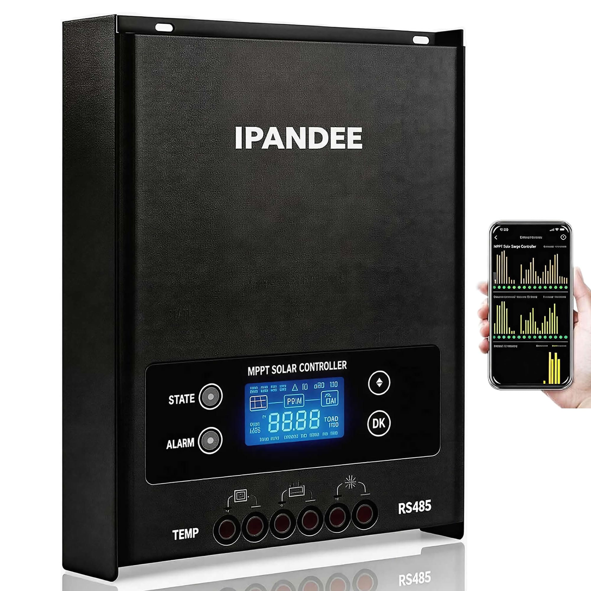
Image 1: Overview of the ipandee 100A MPPT Solar Charge Controller, highlighting its continuous 100A output and robust design.
2. Safety Instructions
Observe the following safety precautions during installation and operation:
- Ensure all wiring is correctly polarized. Incorrect polarity can damage the controller and connected devices.
- Always connect the battery to the charge controller first, then the solar panel, and finally the load. Disconnect in reverse order.
- Do not attempt to disassemble or repair the controller. Refer to qualified personnel for service.
- Install the controller in a well-ventilated area, away from flammable materials and direct sunlight.
- Use appropriate circuit breakers or fuses for all connections to prevent overcurrent damage.
- Wear protective eyewear and gloves when working with batteries and solar panels.
3. Product Features
3.1 Continuous 100A Output
The controller provides a true 100A continuous charging current, designed to maintain full output even under demanding conditions without derating. This ensures reliable power for various applications, including off-grid homes, RVs, boats, and security systems.
3.2 High Voltage Input and MPPT Efficiency
It supports a maximum solar array input voltage of 250V DC, allowing for flexible high-voltage panel configurations and reduced cable loss over long distances. The advanced 4th-generation MPPT algorithm achieves 99.5% tracking efficiency, maximizing energy harvest from your solar panels.

Image 2: Graph illustrating the superior MPPT tracking efficiency of the controller compared to other systems.
3.3 Durability and Compliance
Constructed with industrial-grade components and enhanced thermal management, the controller is designed for a 10-year operational lifespan. It complies with CE, FCC Part 15 Class B, and RoHS 3 standards, ensuring safe and reliable operation.
3.4 Automatic Voltage Detection and Battery Compatibility
The controller automatically detects 12V, 24V, 36V, or 48V system voltages. It is compatible with a wide range of battery types, including LiFePO4, Lithium-ion, AGM, Gel, Flooded, and standard Lead-Acid batteries, offering pre-configured charging profiles for optimized performance.

Image 3: Diagram showing compatibility with various battery types including Flooded, Sealed, Gel, Lithium (LiFePO4), and AGM.
3.5 Integrated Protection Features
The device includes comprehensive multi-layer protection mechanisms to safeguard your solar array, batteries, and loads. These include:
- Reverse polarity protection (PV input & battery output)
- Overcharge and over-discharge protection
- Short-circuit protection
- Overheat protection
- Over-current protection
- Lightning surge protection
- Nighttime reverse current protection

Image 4: Visual representation of the controller's full safety protection features, including overvoltage, undervoltage, overcharge, input reverse connection, overheat, and short circuit protection.
3.6 Monitoring and Connectivity
Real-time monitoring of voltage, current, battery state of charge (SOC), and system status is available via free PC software or an RS485/USB connection. An optional Bluetooth module (sold separately) allows for wireless monitoring through the official ipandee app on iOS/Android devices. Ensure to use genuine ipandee Bluetooth modules for guaranteed compatibility.

Image 5: Illustration of the wireless monitoring system, showing the controller, optional Bluetooth module, and smartphone app interface.
4. Setup and Installation
4.1 Wiring Diagram
Refer to the diagram below for proper connection of the solar panel, battery, and load to the charge controller.

Image 6: Detailed wiring diagram showing connections for solar panels, battery, inverter, and various loads (speaker, TV, fan, computer).
4.2 Connection Steps
- Connect the battery to the charge controller first. Ensure correct polarity.
- Connect the DC load to the controller (if a DC output is required).
- Connect the solar panel array to the controller.
4.3 Disconnection Steps
- Disconnect the solar panel first.
- Disconnect the load.
- Finally, disconnect the battery.

Image 7: Examples of the solar charge controller installed in various applications, including an outdoor shed, RV interior, marine vessel, and residential outdoor setup.
5. Operating Instructions
5.1 LCD Display Overview
The controller features a clear backlight LCD display that provides real-time data and status indications. This includes battery system voltage, load status, MPPT charging status, charging current, battery SOC, and battery type.

Image 8: Close-up view of the controller's LCD display and various ports, including temperature sensor interface, solar panel (PV) interface, battery interface (BAT), LOAD interface, and RJ45 serial communication port.
5.2 LED Indicators
The controller includes LED indicators for charging status and fault conditions:
- State LED:
- Flashes fast: Fast charging state
- Flashes slowly: Constant voltage charging state
- Always on: Floating charging state or standby mode
- Alarm LED:
- Stays on: Fault condition
- Off: Running normally
5.3 Load Control Modes
The controller offers four load control modes to meet various usage needs:
- Normal On/Off Mode: Manual control of the load.
- Optical Control Mode: Load turns on automatically at dusk and off at dawn.
- Dual-Period Timing Control Mode: Allows setting two distinct time periods for load operation.
- Fixed Time Light Control Mode: Load operates for a set duration after dusk.

Image 9: Diagram illustrating the four available load control modes: Normal On/Off, Optical control, Dual-period timing control, and Fixed time light control.
5.4 Lithium Battery Activation
The controller is capable of activating fully discharged LiFePO4 batteries by regulating the charge current and voltage, helping to restore them to an operational state.

Image 10: Illustration demonstrating the controller's ability to activate a fully discharged lithium battery.
6. Maintenance
Regular maintenance ensures the longevity and optimal performance of your solar charge controller:
- Periodically inspect all wiring connections for tightness and corrosion.
- Clean the controller's exterior with a dry cloth to remove dust and debris. Ensure ventilation openings are clear.
- Check the battery terminals for corrosion and clean if necessary.
- Monitor the LCD display for any error codes or unusual readings.
- Ensure the installation environment remains within the specified temperature and humidity ranges.
7. Troubleshooting
If you encounter issues, refer to the following common problems and solutions:
| Problem | Possible Cause | Solution |
|---|---|---|
| No display/Power off | Battery not connected or low voltage; reversed battery polarity; loose connection. | Check battery connections and voltage. Ensure correct polarity. Tighten connections. |
| Battery not charging | Solar panel not connected; low solar input; PV reverse polarity; fault indicator on. | Check solar panel connections. Verify sufficient sunlight. Correct PV polarity. Refer to fault codes if displayed. |
| Load not working | Load disconnected; overcurrent protection; battery low voltage; load control mode settings. | Check load connections. Reduce load. Charge battery. Adjust load control mode settings. |
| Overheat alarm | Poor ventilation; excessive ambient temperature; continuous high load. | Ensure adequate airflow around the controller. Relocate to a cooler environment if possible. Reduce load if sustained. |
For issues not covered here, or if problems persist, contact customer support.
8. Specifications
| Specification | Value |
|---|---|
| Brand | ipandee |
| Model Number | ESF48H100 |
| Rated Charge Current | 100A |
| Max PV Input Voltage | 250V |
| System Voltage | 12V/24V/36V/48V Auto |
| MPPT Tracking Efficiency | 99.5% |
| Material | Metal |
| Product Dimensions (L x W x H) | 24L x 8.5W x 30.5H centimetres |
| Item Weight | 3.4 kg |
| Display Type | LCD |
| Included Components | 1 x MPPT Solar Charge Controller |
9. Support
For technical assistance or inquiries regarding your ipandee 100A MPPT Solar Charge Controller, please refer to the official ipandee support channels. Ensure to use genuine ipandee accessories, such as the Bluetooth module, for full technical support and compatibility.