1. Introduction
This manual provides essential information for the installation, operation, and maintenance of the Generic DAA78L 13127-1 348.01404.0011 Motherboard. Please read this manual thoroughly before installation and keep it for future reference.
The Generic DAA78L 13127-1 348.01404.0011 Motherboard (Model 6524285428570) is designed for compatibility with TC-120 and XC-120 systems, offering reliable performance for your computing needs.
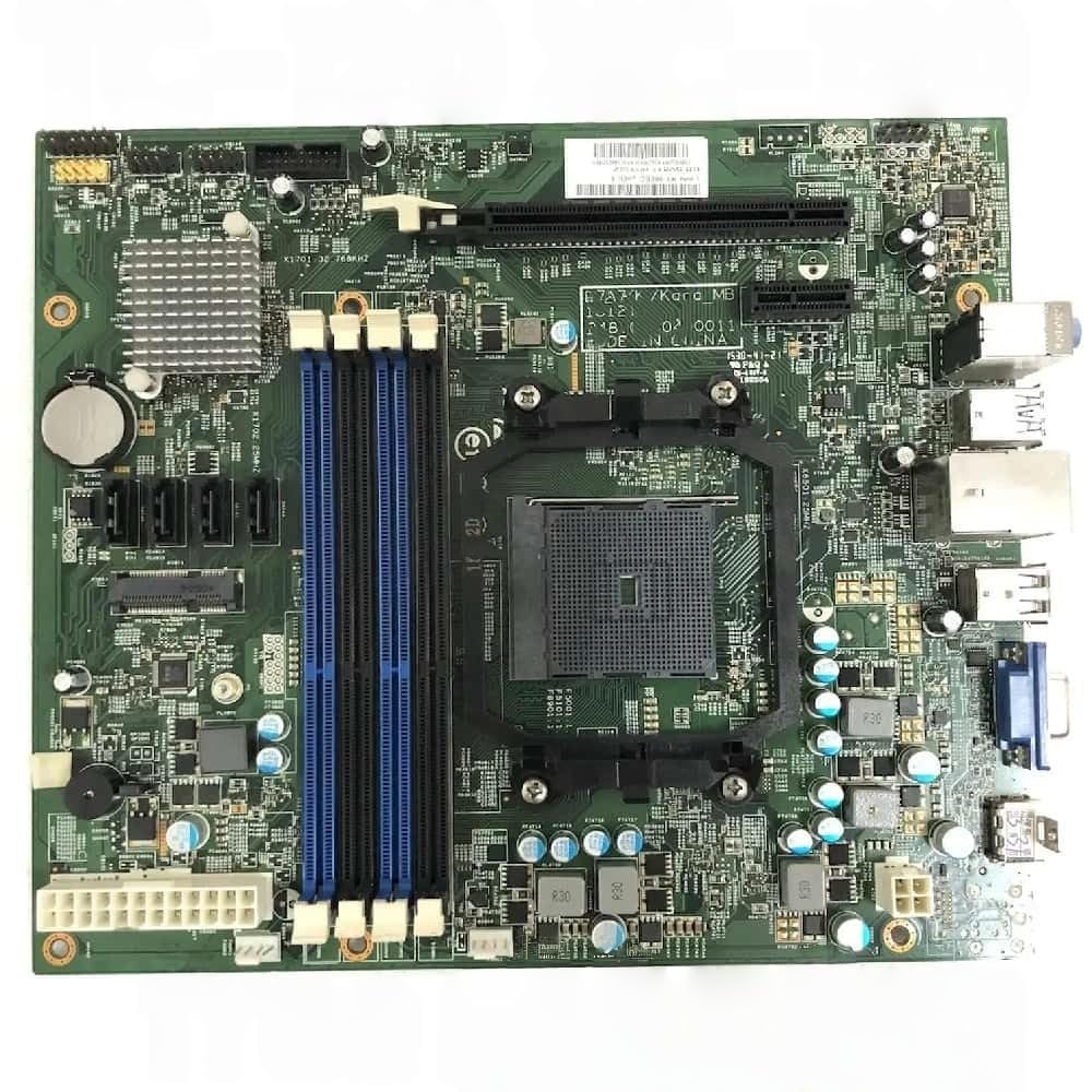
Figure 1: Generic DAA78L 13127-1 348.01404.0011 Motherboard. This image displays the main components and layout of the motherboard.
2. Setup and Installation
2.1 Safety Precautions
- Always disconnect power before installing or removing components.
- Wear an anti-static wrist strap to prevent electrostatic discharge (ESD) damage.
- Handle the motherboard by its edges, avoiding contact with components and connectors.
2.2 Component Installation
- Prepare the Chassis: Ensure your computer case is ready for motherboard installation. Install standoffs if necessary.
- Install CPU: Carefully align the CPU with the socket on the motherboard. Lower the CPU into place without force. Secure the CPU retention arm.
- Install CPU Cooler: Attach the CPU cooler according to its specific instructions. Ensure proper thermal paste application.
- Install RAM: Open the DIMM slot clips. Align the RAM module notch with the slot key. Press firmly on both ends until the clips lock into place.
- Mount Motherboard: Carefully place the motherboard into the chassis, aligning the screw holes with the standoffs. Secure with screws.
- Connect Power: Connect the 24-pin ATX power connector and the 4/8-pin CPU power connector from your power supply to the motherboard.
- Connect Peripherals: Connect front panel headers (power switch, reset switch, USB, audio), SATA devices, and any expansion cards (e.g., graphics card).
3. Operating Instructions
3.1 First Boot
- After all components are installed and connected, connect your monitor, keyboard, and mouse.
- Power on the system. The system should display the BIOS/UEFI splash screen.
- Access the BIOS/UEFI setup by pressing the designated key (usually DEL or F2) during startup.
3.2 BIOS/UEFI Configuration
The BIOS/UEFI interface allows you to configure system settings, boot order, and hardware parameters. Refer to your system's specific BIOS/UEFI manual for detailed instructions on navigation and settings.
3.3 Driver Installation
After installing your operating system, install the necessary drivers for the motherboard's chipsets, audio, network, and other integrated components. These drivers are typically provided on a support CD or can be downloaded from the manufacturer's website.
4. Maintenance
- Dust Removal: Regularly clean dust from the motherboard and other components using compressed air. Ensure the system is powered off and unplugged before cleaning.
- BIOS/UEFI Updates: Periodically check the manufacturer's website for BIOS/UEFI updates. Updates can improve stability, compatibility, and performance. Follow update instructions carefully to avoid system damage.
- Cable Management: Ensure internal cables are neatly routed to improve airflow and prevent interference.
5. Troubleshooting
| Problem | Possible Cause | Solution |
|---|---|---|
| System does not power on. | Power cables not connected; faulty power supply; front panel header incorrect. | Check 24-pin and CPU power connectors. Verify power supply functionality. Recheck front panel connections. |
| No display output. | Monitor cable loose; graphics card not seated; RAM issues. | Ensure monitor cable is secure. Reseat graphics card. Reseat RAM modules. Test with one RAM stick. |
| System beeps during startup. | Hardware error indicated by beep codes. | Consult your motherboard's specific beep code documentation to identify the component causing the error (e.g., RAM, graphics card). |
| Operating system fails to load. | Incorrect boot order; corrupted OS installation; faulty storage drive. | Check boot order in BIOS/UEFI. Attempt OS repair or reinstallation. Test storage drive. |
6. Specifications
The following specifications are for the Generic DAA78L 13127-1 348.01404.0011 Motherboard:
- Model Number: 6524285428570
- Part Number: DAA78L 13127-1 348.01404.0011
- Compatibility: Suitable for TC-120 and XC-120 systems.
- Manufacturer: Generic
- ASIN: B0GF1RRVKF
- First Available: January 5, 2026
- Note: Detailed specifications regarding chipset, CPU socket, RAM slots, expansion slots, and I/O ports should be obtained from the official product page or manufacturer's documentation.
7. Warranty and Support
7.1 Warranty Information
For warranty details, please refer to the specific terms and conditions provided by the seller or manufacturer at the time of purchase. Typically, electronic components come with a limited warranty covering manufacturing defects.
Note: Unauthorized modifications or improper installation may void the product warranty.
7.2 Technical Support
For technical assistance, troubleshooting, or further inquiries, please contact the seller or the manufacturer's support channels. Have your product part number (DAA78L 13127-1 348.01404.0011) and purchase information ready when contacting support.
You may also find additional resources and FAQs on the manufacturer's official website.