1. Introduction
The WALFRONT REX C100 is a high-precision PID temperature controller designed for various industrial and commercial applications. It utilizes advanced self-tuning PID technology to ensure rapid temperature adjustments with minimal overshoot, providing accurate and stable temperature control. This manual provides essential information for the safe and efficient operation of your REX C100 controller.
Key applications include food processing, chemical industries, injection molding, and other environments requiring precise thermal monitoring and control.
2. Safety Information
- Electrical Hazard: Always disconnect power before installation, wiring, or maintenance to prevent electric shock.
- Proper Wiring: Ensure all wiring connections are secure and comply with local electrical codes. Incorrect wiring can cause damage to the device or pose a fire hazard.
- Environmental Conditions: Operate the controller within the specified temperature and humidity ranges. Avoid exposure to corrosive gases, excessive dust, or moisture.
- Qualified Personnel: Installation and wiring should only be performed by qualified personnel.
- Intended Use: Use the device only for its intended purpose as a temperature controller. Do not modify the device.
3. Package Contents
Verify that all items are present in the package:
- 1 x WALFRONT REX C100 PID Temperature Controller
4. Product Overview
The REX C100 features a clear digital display and intuitive controls for easy operation.

Figure 4.1: Front Angled View of REX C100 Controller. This image displays the front panel of the REX C100 PID Temperature Controller from an angled perspective. It clearly shows the dual digital displays for Process Value (PV) and Set Value (SV), along with indicator lights for ALM1, ALM2, OUT1, and AT. The 'SET' button and arrow keys are visible at the bottom left.
Front Panel Description
- PV Display (Upper): Shows the current Process Value (measured temperature).
- SV Display (Lower): Shows the Set Value (target temperature).
- ALM1 Indicator: Illuminates when Alarm 1 is active.
- ALM2 Indicator: Illuminates when Alarm 2 is active.
- OUT1 Indicator: Illuminates when the control output is active.
- AT Indicator: Illuminates during auto-tuning (self-tuning PID).
- SET Button: Used to enter parameter setting mode and confirm selections.
- Arrow Buttons (Up/Down/Left): Used to navigate menus and adjust values.
Rear Panel and Terminals
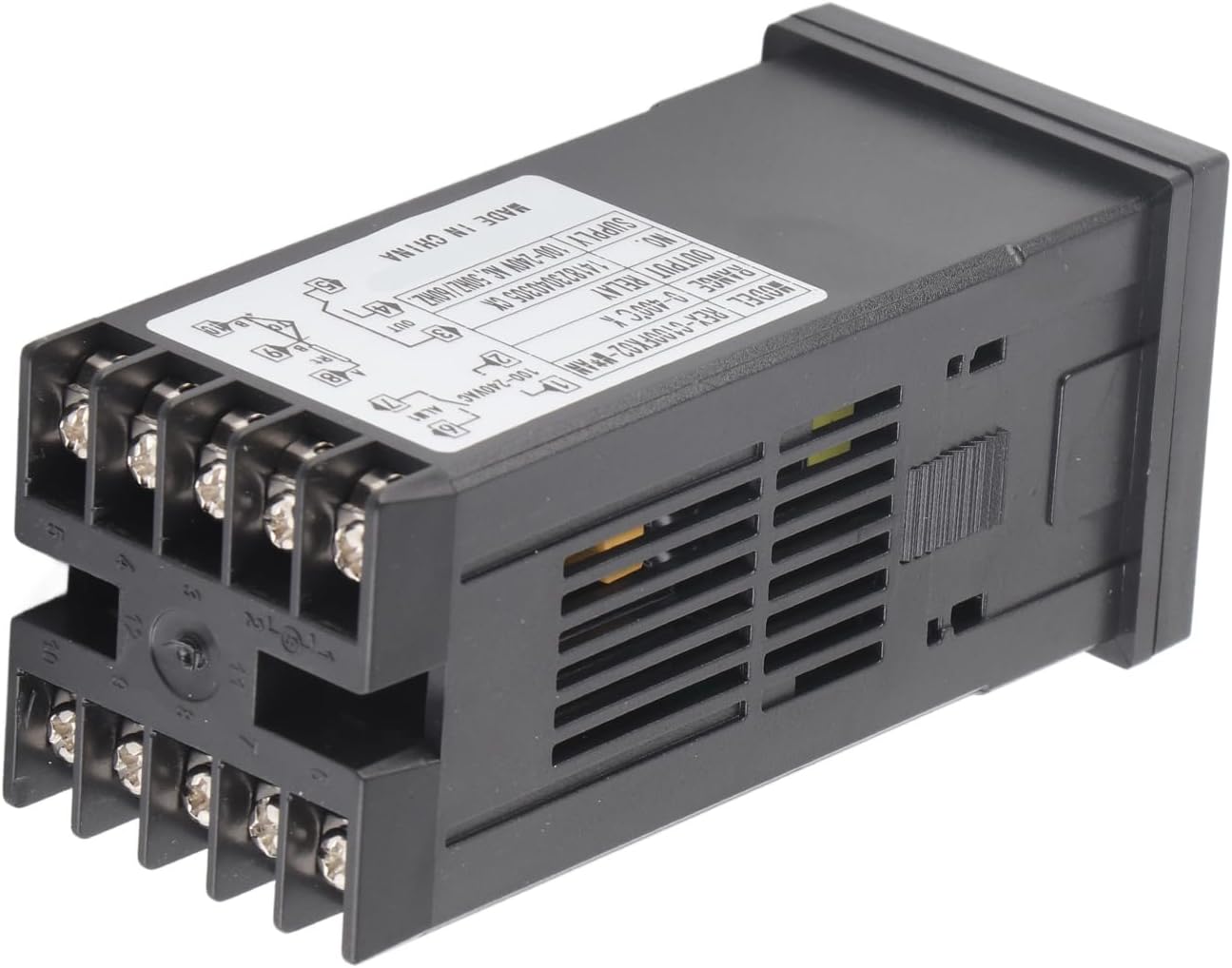
Figure 4.2: Rear View with Wiring Terminals. This image shows the back of the REX C100 controller, highlighting the screw terminals for electrical connections and the product label with specifications and a basic wiring diagram.
The rear panel contains the screw terminals for power input, sensor input, and control outputs. Refer to the wiring diagram on the device label for precise connections.
5. Setup
5.1 Mounting
The REX C100 is designed for panel mounting. Cut an appropriate opening in your control panel according to the device dimensions. Insert the controller into the opening and secure it using the provided mounting brackets from the rear.

Figure 5.1: REX C100 with Mounting Bracket. This image shows the REX C100 controller with its black plastic mounting bracket, illustrating how the device is secured into a panel cutout.
5.2 Wiring
WARNING: Ensure power is disconnected before performing any wiring.
Refer to the wiring diagram printed on the side label of the controller for accurate connections. A typical wiring configuration is as follows:

Figure 5.2: Wiring Diagram on Product Label. This image provides a close-up of the REX C100's side label, which includes a comprehensive wiring diagram for power, sensor input, and output connections.
- Power Supply (Terminals 1 & 2): Connect your 100-240VAC, 50/60Hz power source here.
- Output (OUT1) (Terminals 3, 4, 5): These are relay contacts. Connect your heating or cooling element through these terminals. The diagram shows Normally Open (NO) and Common (COM) connections.
- Alarm 1 (ALM1) (Terminals 6 & 7): Connect external alarm devices here.
- Alarm 2 (ALM2) (Terminals 8 & 9): Connect external alarm devices here.
- Sensor Input (Terminals 10 & 11): Connect your K-type thermocouple here. Ensure correct polarity for accurate readings.
After wiring, double-check all connections before applying power.
6. Operating Instructions
6.1 Power On
Once wired correctly, apply power to the controller. The PV display will show the current temperature measured by the thermocouple, and the SV display will show the set target temperature.
6.2 Setting the Target Temperature (SV)
- Press the SET button once. The SV display will begin to flash.
- Use the Up and Down arrow buttons to adjust the target temperature. The Left arrow button can be used to shift the cursor for faster adjustment of individual digits.
- Press the SET button again to confirm the new SV. The display will stop flashing, and the controller will begin to regulate the temperature to the new set point.
6.3 PID Auto-Tuning
The REX C100 features an expert self-tuning PID function. Auto-tuning helps the controller learn the characteristics of your specific heating/cooling system to optimize control performance and minimize overshoot or undershoot.
To initiate auto-tuning:
- Ensure the system is at a stable temperature, preferably near your desired set point.
- Press and hold the SET button for approximately 3-5 seconds until the controller enters the parameter setting menu.
- Navigate through the parameters (using arrow keys) until you find the auto-tuning parameter (often labeled 'AT' or similar).
- Set the auto-tuning parameter to '1' (or 'ON') and confirm with the SET button. The 'AT' indicator light on the front panel will illuminate.
- The controller will cycle the output to determine the optimal PID parameters. This process may take some time (e.g., several heating/cooling cycles).
- Once auto-tuning is complete, the 'AT' indicator will turn off, and the controller will operate with the newly optimized PID parameters.
Note: Specific parameter codes and navigation may vary slightly. Refer to the detailed programming manual (if available) for advanced settings.
6.4 Alarm Settings
The REX C100 includes two alarm outputs (ALM1, ALM2). These can be configured for various alarm types (e.g., high limit, low limit, deviation) and hysteresis. Access these settings through the parameter menu by pressing and holding the SET button.
7. Maintenance
- Cleaning: Clean the front panel with a soft, dry cloth. Do not use abrasive cleaners or solvents.
- Environmental Check: Periodically inspect the operating environment to ensure it remains free of corrosive gases, excessive dust, and moisture.
- Connection Check: Occasionally check wiring connections for tightness, especially in environments with vibration.
- Sensor Inspection: Inspect the thermocouple for any signs of damage or corrosion that could affect accuracy.
8. Troubleshooting
| Problem | Possible Cause | Solution |
|---|---|---|
| Controller does not power on. | No power supply; incorrect wiring. | Check power connections (Terminals 1 & 2). Ensure voltage is within 100-240VAC. |
| PV display shows 'HHHH' or 'LLLL'. | Thermocouple open circuit or reverse connection. | Check thermocouple wiring (Terminals 10 & 11) for breaks or incorrect polarity. Ensure it is a K-type thermocouple. |
| Temperature reading is inaccurate. | Incorrect sensor type selected (if configurable); sensor fault; environmental interference. | Verify sensor type. Check sensor for damage. Ensure proper shielding if in an electrically noisy environment. |
| Output (OUT1) not activating. | SV not reached; output parameter incorrect; wiring issue. | Check SV. Verify output control mode. Inspect output wiring (Terminals 3, 4, 5). |
| Temperature overshoots/undershoots target. | PID parameters not optimized. | Perform PID auto-tuning (refer to Section 6.3). |
9. Specifications
| Feature | Specification |
|---|---|
| Model | REX-C100 |
| Control Type | Temperature |
| Control Mode | RELAY (Output) |
| Measurement Objects | All objects (with compatible K-type thermocouple) |
| Temperature Measurement Error | ±1% (℃) |
| Working Voltage | 100-240VAC |
| Measurement Accuracy | ±0.5%FS |
| Resolution | 14Bit |
| Insulation Strength | 1500VAC/1 minute |
| Weight | 164g (approx. 6 ounces) |
| Temperature Range (K-Type) | 0-400°C (32-752°F) |
| Operating Environment | 0-50℃ (32-122°F), 30-85% RH, free of corrosive gas |
| Package Dimensions | 5.51 x 2.76 x 2.36 inches |
10. Warranty and Support
This product is covered by a standard manufacturer's warranty against defects in materials and workmanship. Please refer to your purchase documentation for specific warranty terms and duration.
For technical support, troubleshooting assistance, or warranty claims, please contact your retailer or the manufacturer directly. Keep your purchase receipt as proof of purchase.