
1. Introduction
The eletechsup ES30E08 is an 8-channel WiFi Relay 30Pin ESP32 Programmable Expansion Board designed for integration into Arduino and IoT network projects. This module provides Modbus RS485 communication, 8 digital inputs (DI), and 8 relay outputs (DO), enabling versatile control and monitoring capabilities. It is important to note that the ES30E08 functions as an expansion board and requires a separate 30PIN ESP32 development board for operation and programming.
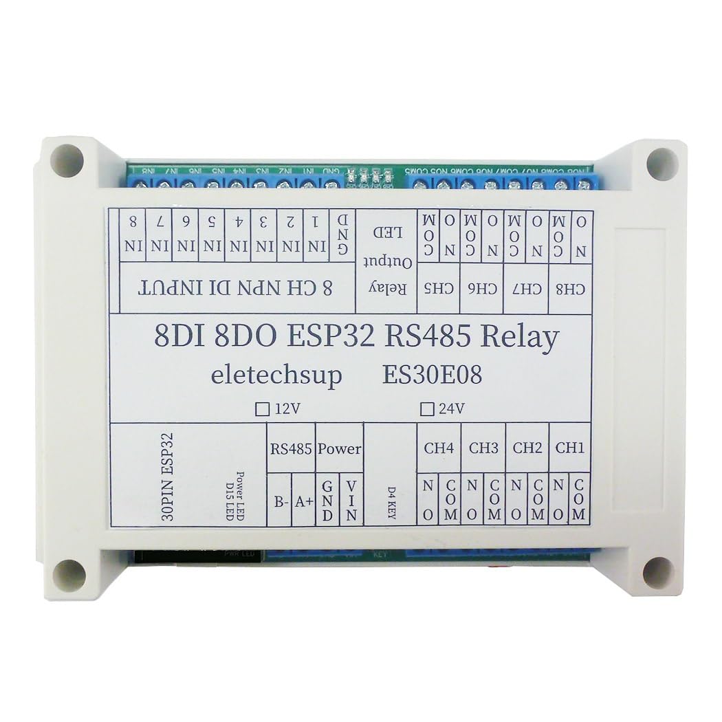
Figure 1: eletechsup ES30E08 DC 24V Expansion Board. This image shows the top view of the ES30E08 module, highlighting its 24V DC variant. It also includes a note indicating that an ESP32 board is not included and must be prepared separately.
2. Product Overview
The ES30E08 module integrates several key components to facilitate its functionality:
- 30PIN ESP32 Slot: For connecting a compatible ESP32 development board.
- RS485 Interface: For Modbus communication.
- 8x 10A Relay Outputs: For controlling external devices.
- 8x Opto-isolated Digital Inputs (NPN type): For sensing external signals.
- 1x LED Indicator: For status indication.
- 1x Button: For user interaction.

Figure 2: Internal view of the ES30E08 PCB. This image displays the internal circuit board of the ES30E08, clearly labeling key components such as the 30-pin ESP32 socket, 8 NPN Digital Inputs, 8 10A Relay Outputs, 1 LED Output, 1 Button Input, 1 RS485 BUS, and power supply input (DC 12V/24V).
3. Features
- Operating Voltage: DC 12V/24V (model specific).
- Relay Channels: 8 channels, each capable of switching up to 10A.
- Digital Inputs: 8 opto-isolated inputs (low level trigger, NPN type).
- Communication: WiFi (via ESP32), Modbus RS485.
- Expansion: Designed for 30PIN ESP32 boards.
- Applications: Suitable for DIY smart home controllers, RS485 master-slave devices, remote control switches, timing functions, and more.

Figure 3: ES30E08 Onboard Resources. This image highlights the key onboard resources of the ES30E08, including 8-channel NPN Digital Input, 8-channel 10A Relay Output, 1-channel Button Input, 1-channel LED Output, and 1-channel RS485 BUS, emphasizing its multi-function programmable relay capabilities.
4. Specifications
| Parameter | Value |
|---|---|
| Operating Voltage | DC 24V (for this variant) |
| Operating Current (Standby, Digital tube OFF) | 13mA |
| Operating Current (Standby, Digital tube ON) | 51mA |
| Current per Relay (approx.) | 25-30mA (additional per active relay) |
| Relay Output Current | Up to 10A per channel |
| Digital Inputs | 8x Opto-isolated (low level trigger, NPN type) |
| Communication Interface | RS485 |
| ESP32 Compatibility | 30PIN ESP32 boards (25.4mm pin width) |
| Dimensions | 144mm x 90mm x 40mm |
| Weight | 220g |
5. Setup
5.1. Prerequisites
Before using the ES30E08 expansion board, you must have a compatible 30PIN ESP32 development board. The ESP32 board should have a pin width of approximately 25.4mm (board width about 28mm) to fit correctly into the ES30E08 slot. The ES30E08 cannot operate independently.
5.2. ESP32 Board Installation
- Carefully align the 30 pins of your ESP32 board with the corresponding slot on the ES30E08 expansion board.
- Gently press the ESP32 board into the slot until it is securely seated. Ensure all pins are correctly inserted and no pins are bent.
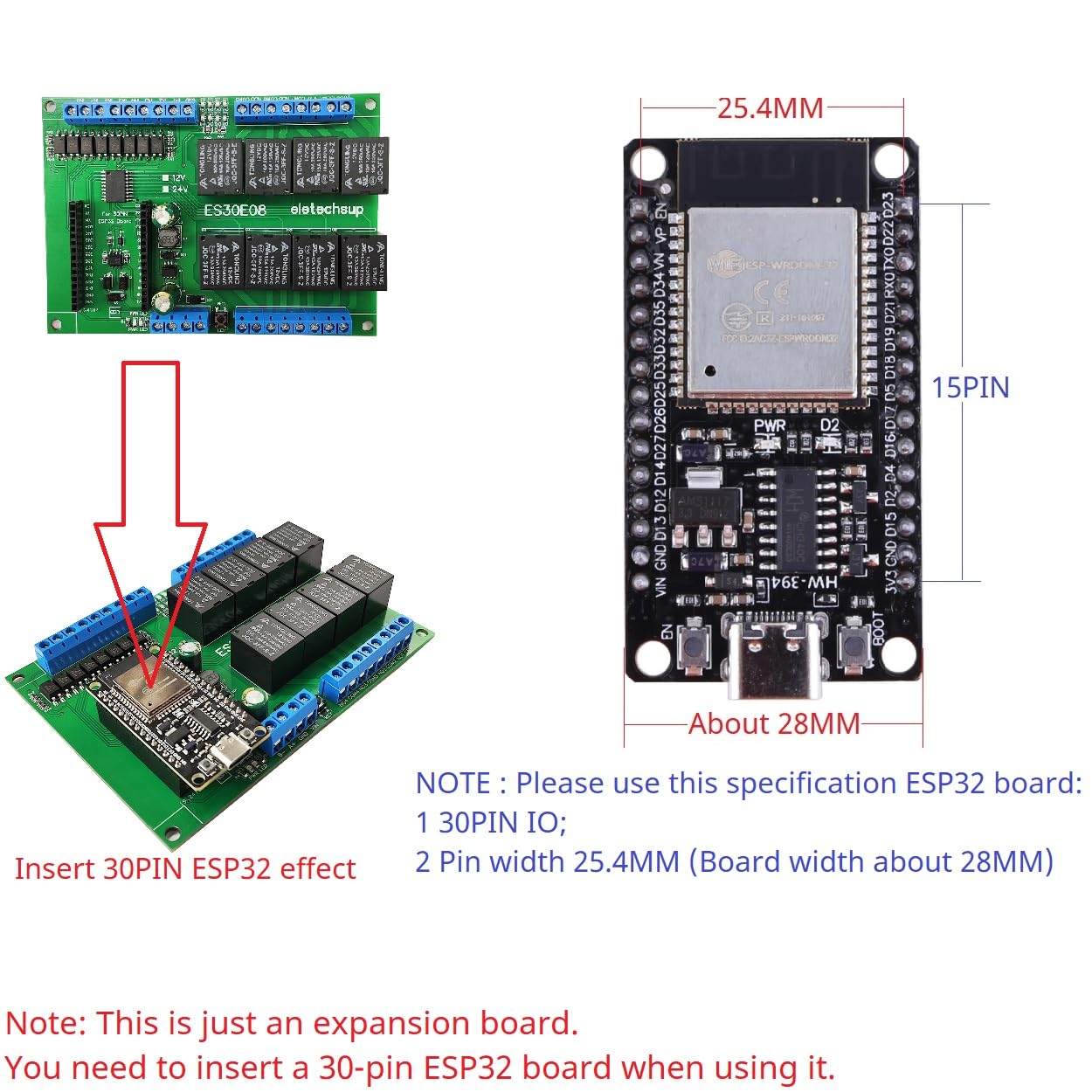
Figure 4: ESP32 Board Insertion. This image illustrates the process of inserting a 30PIN ESP32 board into the ES30E08 expansion board, emphasizing the correct orientation and fit. It also specifies the required ESP32 board dimensions (30PIN IO, 25.4mm pin width).
5.3. Power Connection
Connect a DC 24V power supply to the designated power input terminals on the ES30E08 board. Ensure correct polarity (GND and VIN). This variant is designed for DC 24V operation.
5.4. Wiring Diagram
Refer to the wiring diagram below for connecting external devices to the ES30E08 module. This includes connections for RS485, digital inputs, and relay outputs.

Figure 5: ES30E08 Wiring Diagram. This diagram provides a visual guide for connecting the ES30E08 module. It shows the 8-channel NPN Digital Input (3.2-24V) connections, RS485 connections (A+, B-, GND), and relay output connections (NO, COM) for controlling loads with DC 1-110V or AC 85-265V.
5.4.1. RS485 Connection
Connect your RS485 communication lines to the A+ and B- terminals. The GND terminal is also available for common ground reference.
5.4.2. Digital Inputs (8CH NPN DI)
The 8 digital inputs (IN1-IN8) are opto-isolated and designed for low-level trigger (NPN type) signals ranging from 3.2V to 24V. Connect your input signals to the respective IN terminals and the common ground to GND.
5.4.3. Relay Outputs (8CH DO)
Each of the 8 relay channels provides Normally Open (NO) and Common (COM) terminals. Connect your load to the COM and NO terminals for switching. The relays can handle loads up to 10A.
6. Operating Instructions
The ES30E08 is a programmable expansion board. Its functionality is entirely dependent on the code uploaded to the connected ESP32 board. eletechsup provides basic Arduino code for hardware testing, but advanced functionalities require custom programming by the user.
With appropriate ESP32 code, the ES30E08 can be configured for various applications, including but not limited to:
- WiFi remote control switching.
- 8x RS485 Digital Input/Digital Output (DI-DO) operations.
- RS485 Master-Slave device functionality (e.g., for PLC/MCU integration).
- Motor forward and reverse control.
- LED controller applications.
- Various timing functions: Timing on, Timing off, Power-up delay, Trigger delay, Infinite loop delay, Finite cyclic delays, Power sequencer.
7. Pin Mapping
The following table details the pin mapping between the ES30E08 expansion board ports and the 30PIN ESP32 pins.
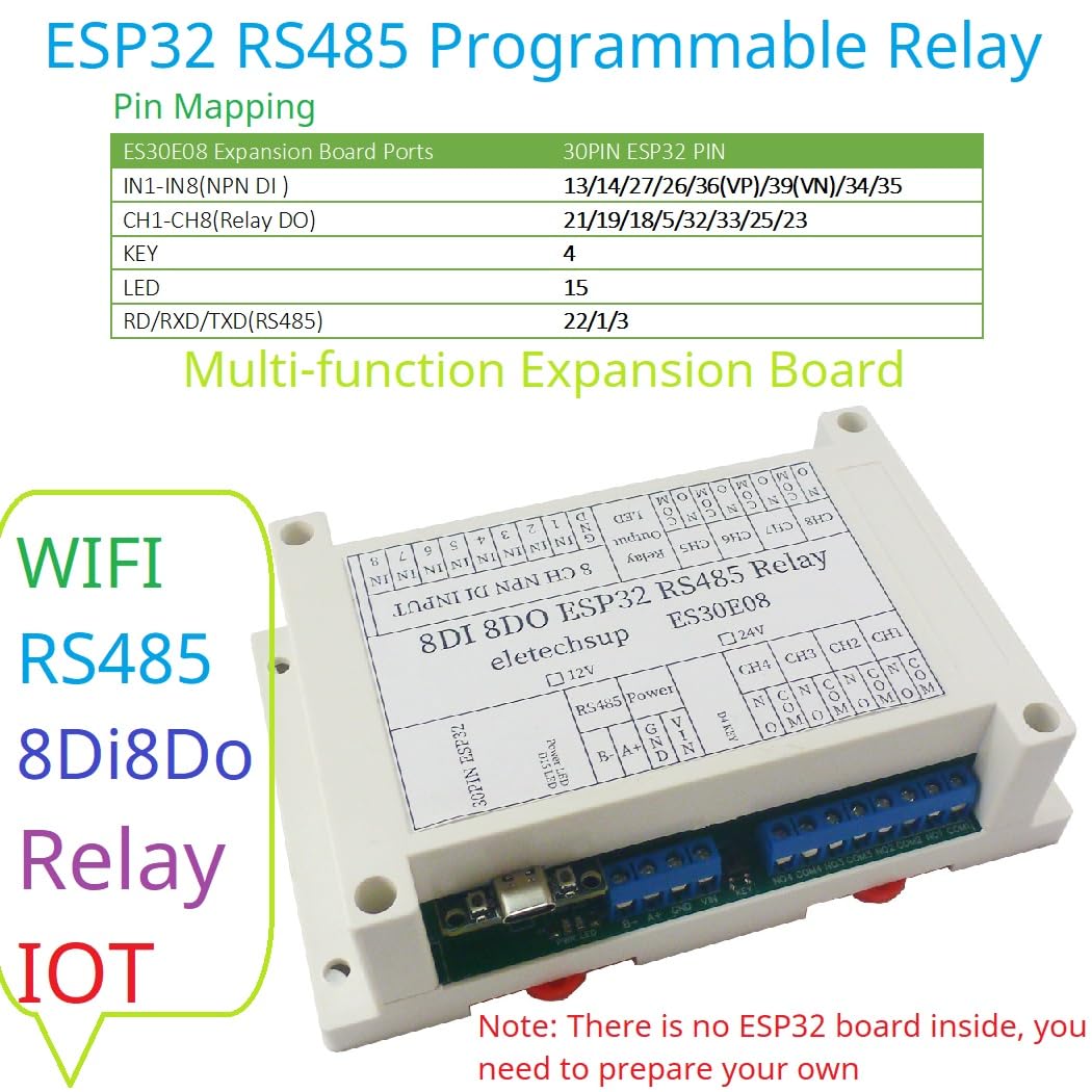
Figure 6: ES30E08 Pin Mapping. This image presents a table showing the pin assignments for the ES30E08 expansion board ports (IN1-IN8, CH1-CH8, KEY, LED, RD/RXD/TXD) and their corresponding 30PIN ESP32 pins.
| ES30E08 Expansion Board Ports | 30PIN ESP32 Pin |
|---|---|
| IN1-IN8 (NPN DI) | 13/14/27/26/36(VP)/39(VN)/34/35 |
| CH1-CH8 (Relay DO) | 21/19/18/5/32/33/25/23 |
| KEY | 4 |
| LED | 15 |
| RD/RXD/TXD (RS485) | 22/1/3 |
8. Applications
The ES30E08 can be utilized as an RS485 master device to control various RS485 slave devices, serving as an alternative to PLCs, PCs, or touch screens in certain applications. Its programmable nature with an ESP32 board allows for flexible implementation in industrial automation, smart home systems, and custom IoT projects.

Figure 7: RS485 Master Device Application. This image illustrates how the ES30E08 can be used as an RS485 master device, connecting to and controlling multiple RS485 slave devices (e.g., 15AI-1VI, 22AI-2VI modules) via the RS485 BUS. It emphasizes that an ESP32 board must be plugged in for proper functionality.
9. Troubleshooting
- Module Not Powering On: Ensure the DC 24V power supply is correctly connected with the right polarity and is providing sufficient current. Verify the ESP32 board is properly seated.
- Relays Not Activating: Check your ESP32 code to ensure the correct GPIO pins are being controlled. Verify the power supply to the ES30E08 is stable.
- Digital Inputs Not Responding: Confirm that input signals are within the 3.2V-24V range and are NPN type (low-level trigger). Check wiring for continuity and correct connection to IN terminals and GND.
- RS485 Communication Issues: Verify A+ and B- connections are not reversed. Ensure termination resistors are correctly used if necessary in your RS485 network. Check baud rates and communication protocols in your ESP32 code.
- ESP32 Not Detected/Working: Ensure the ESP32 board is fully inserted into the 30PIN slot. Confirm the ESP32 board itself is functional and correctly programmed. Remember, the ES30E08 is an expansion board and requires a working ESP32.
10. Maintenance
The ES30E08 module is designed for reliable operation with minimal maintenance. To ensure longevity and proper function:
- Keep the module in a clean, dry environment, away from excessive dust, moisture, and corrosive substances.
- Avoid exposing the module to extreme temperatures or direct sunlight.
- Ensure proper ventilation if enclosed, especially when relays are frequently switching high currents, to prevent overheating.
- Periodically inspect wiring connections for looseness or damage.
11. Warranty and Support
This product is an expansion board that requires user programming of a separate ESP32 board. While eletechsup provides basic Arduino code for hardware testing, additional code development and advanced functionalities are the responsibility of the user. Technical support for custom code or specific application development is not provided.
For hardware-related issues or defects, please refer to the retailer's return and warranty policy. Ensure all components are handled with care during installation and operation to prevent damage.


