
MAYILON MY8906B TRMS Digital Multimeter User Manual
Model: MY8906B
1. Introduction
The MAYILON MY8906B is a True RMS (TRMS) digital multimeter designed for accurate and reliable electrical measurements. It features a full-featured overload protection circuit and is suitable for a wide range of applications, including household electrical maintenance, automotive circuit troubleshooting, and testing of electronic devices. This manual provides essential information for safe and effective use of the multimeter.
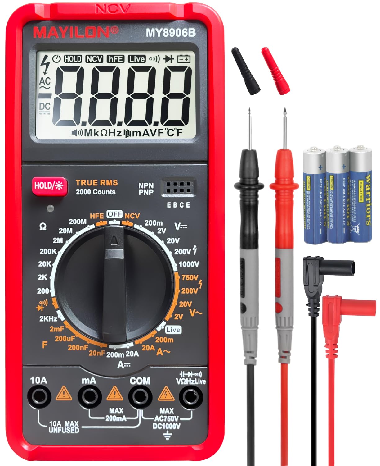
Image 1.1: The MAYILON MY8906B Multimeter, highlighting its 2000 counts display and various measurement functions such as AC/DC Voltage, AC/DC Current, Resistance, Capacitance, Diode, Transistor (HFE), NCV, Live Wire, Backlight, Continuity, Data Hold, and Frequency.
The MY8906B multimeter is capable of measuring:
- AC/DC Voltage (up to 750V AC / 1000V DC)
- AC/DC Current
- Resistance
- Capacitance
- Diodes
- Transistors (hFE)
- Frequency
- Continuity
- Non-Contact Voltage (NCV) detection
- Live Wire detection
2. Safety Information
Always adhere to safety precautions when using any electrical testing equipment. Failure to do so may result in electric shock, injury, or damage to the meter or equipment under test.
- The MY8906B multimeter complies with IEC-61010-1 CAT II 600V safety rating.
- It features double insulation and fuse protection against burnout.
- The silicone rubber casing provides effective protection against instrument damage and isolates electric shock risks.
- Do not exceed the maximum input values: DC 1000V / AC 750V.
- Ensure the test leads are in good condition, without any cracks or damaged insulation.
- Always select the correct measurement function and range before connecting the test leads to the circuit.
- When measuring current, ensure the meter is connected in series with the load and the circuit is de-energized before connecting.
- Use caution when working with voltages above 30V AC RMS, 42V peak, or 60V DC, as these pose a shock hazard.
- Replace batteries when the low battery indicator appears to ensure accurate readings.
3. Product Overview
3.1 Included Components
The MAYILON MY8906B Multimeter kit includes:
- MY8906B Digital Multimeter
- Test Probes (Red and Black)
- Batteries (pre-installed or included separately)
- User Manual
3.2 Meter Layout and Features
The multimeter features a clear digital display, a rotary selector dial for function selection, and input jacks for test probes.

Image 3.1: The MY8906B Multimeter's clear display, rotary function selector, and input terminals. The display shows '117.6' for a voltage reading.
- Digital Display: Large, clear display for easy reading of measurements.
- Rotary Selector Dial: Used to select the desired measurement function (Voltage, Current, Resistance, etc.).
- Input Jacks: Terminals for connecting the test probes (COM, VΩmA, 10A).
- Transistor Test Sockets (hFE): Dedicated sockets for testing transistors.
- HOLD Button: Freezes the current reading on the display.
- Backlight Button: Activates the display backlight for improved visibility in low-light conditions.
- NCV/LIVE Button: Toggles between Non-Contact Voltage and Live Wire detection modes.
- Auto Power-Off: The meter automatically shuts down after approximately 15 minutes of inactivity to conserve battery life. This feature can be canceled.
4. Setup
4.1 Battery Installation
The multimeter requires batteries for operation. If the display does not turn on or shows a low battery indicator, replace the batteries.
- Ensure the multimeter is powered off.
- Locate the battery compartment on the back of the meter.
- Use a screwdriver to open the battery compartment cover.
- Insert the new batteries, observing the correct polarity (+ and -).
- Replace the battery compartment cover and secure it with the screw.
4.2 Connecting Test Probes
Connect the test probes to the appropriate input jacks on the multimeter.
- Connect the black test lead to the COM (common) jack.
- For most measurements (Voltage, Resistance, Capacitance, Diode, Frequency, Continuity), connect the red test lead to the VΩmA jack.
- For high current measurements (up to 10A), connect the red test lead to the 10A jack.
5. Operating Instructions
Before taking any measurement, ensure the test leads are correctly connected and the rotary dial is set to the appropriate function and range.
5.1 DC/AC Voltage Measurement
To measure DC or AC voltage:
- Set the rotary dial to the desired DCV (V—) or ACV (V~) range. If the voltage is unknown, start with the highest range and decrease as needed.
- Connect the test probes in parallel across the component or circuit to be measured.
- Read the voltage value on the display.

Image 5.1: Examples of measuring DC voltage in an electrical panel (left) and AC voltage in a circuit breaker box (right) using the MY8906B Multimeter.
5.2 DC/AC Current Measurement
To measure DC or AC current:
- Power off the circuit before connecting the meter.
- Set the rotary dial to the desired DCA (A—) or ACA (A~) range.
- Connect the test probes in series with the circuit. For currents up to 200mA, use the VΩmA jack. For currents up to 10A, use the 10A jack.
- Power on the circuit and read the current value on the display.
- Power off the circuit before disconnecting the meter.

Image 5.2: The MY8906B Multimeter measuring AC current on a circuit board, showing a reading of '0.037 A'.
5.3 Resistance Measurement
To measure resistance:
- Ensure the circuit or component is de-energized before measuring resistance.
- Set the rotary dial to the Ω (Ohms) range.
- Connect the test probes across the component.
- Read the resistance value on the display.

Image 5.3: The MY8906B Multimeter measuring resistance on a circuit board, displaying '1.161 MΩ'.
5.4 Capacitance Measurement
To measure capacitance:
- Ensure the capacitor is fully discharged before measurement.
- Set the rotary dial to the capacitance (——|——) range.
- Connect the test probes across the capacitor terminals.
- Read the capacitance value on the display.

Image 5.4: The MY8906B Multimeter measuring the capacitance of a component, showing a reading of '0.541 uF'.
5.5 Diode Test
To test a diode:
- Ensure the diode is de-energized and disconnected from the circuit.
- Set the rotary dial to the diode (→|—) test function.
- Connect the red probe to the anode and the black probe to the cathode. A forward voltage drop (e.g., 0.5V to 0.7V) should be displayed.
- Reverse the probes. The display should show 'OL' (Open Loop) for a good diode.

Image 5.5: The MY8906B Multimeter performing a diode test on a circuit board, displaying a forward voltage drop of '0.532 V'.
5.6 Transistor (hFE) Test
To test a transistor's hFE (current gain):
- Set the rotary dial to the hFE function.
- Identify if the transistor is NPN or PNP.
- Insert the transistor leads (Emitter, Base, Collector) into the corresponding hFE test sockets on the meter.
- Read the hFE value on the display.

Image 5.6: The MY8906B Multimeter performing a transistor hFE test, showing a reading of '1689'.
5.7 Frequency Measurement
To measure frequency:
- Set the rotary dial to the Hz (Frequency) range.
- Connect the test probes across the signal source.
- Read the frequency value on the display.

Image 5.7: The MY8906B Multimeter measuring frequency from a power outlet, displaying '031.9 Hz'.
5.8 Continuity Test
To test for continuity:
- Ensure the circuit or component is de-energized.
- Set the rotary dial to the continuity (☸) function.
- Connect the test probes across the component or wire.
- If there is continuity (low resistance), the buzzer will sound, and a low resistance value will be displayed. If there is no continuity, 'OL' will be displayed.

Image 5.8: The MY8906B Multimeter performing a continuity test on a wire, showing a reading of '00.28 Ω'.
5.9 Non-Contact Voltage (NCV) Detection
To detect AC voltage without contact:
- Remove the test probes from the meter.
- Set the rotary dial to the NCV mode.
- Bring the NCV sensor (located at the top of the meter) near the wire or outlet.
- If AC voltage is detected, the buzzer will sound, and the NCV indicator will illuminate.

Image 5.9: The MY8906B Multimeter detecting non-contact voltage near a wall outlet, indicated by the NCV symbol and red lights on the display.
5.10 Live Wire Detection
To identify a live conductor using a single probe:
- Set the rotary dial to the LIVE mode.
- Touch the red test probe to the wire or terminal to be tested.
- If the wire is live, the display will show 'LIVE' and the buzzer will sound.

Image 5.10: The MY8906B Multimeter performing a live wire test in an electrical box, indicated by 'LIVE' on the display.
5.11 Data Hold and Backlight
- Data Hold: Press the "HOLD" button to freeze the current reading on the display. Press it again to release.
- Backlight: Press the backlight button to illuminate the display for easier reading in dim environments. Press it again to turn off the backlight.

Image 5.11: User-friendly features of the MY8906B Multimeter, including 15-minute auto-shutdown, option to cancel auto power-off, backlight, and data retention.
6. Maintenance
6.1 Cleaning
Wipe the meter with a damp cloth and mild detergent. Do not use abrasives or solvents. Ensure the meter is dry before use.
6.2 Battery Replacement
Refer to Section 4.1 for battery replacement instructions. Replace batteries promptly when the low battery indicator appears to maintain measurement accuracy.
6.3 Fuse Replacement
If the current measurement function stops working, the fuse may need replacement. Refer to the internal diagram or contact support for specific fuse type and replacement procedure. Always use a fuse with the specified rating.
6.4 Storage
When not in use for extended periods, remove the batteries to prevent leakage. Store the multimeter in a cool, dry place, away from direct sunlight and extreme temperatures.
7. Troubleshooting
| Problem | Possible Cause | Solution |
|---|---|---|
| Meter does not power on. | Dead or incorrectly installed batteries. | Check battery polarity or replace batteries. |
| Display shows "OL" (Overload). | Measurement exceeds selected range or maximum input. | Select a higher range or ensure measurement is within meter's specifications. |
| Inaccurate readings. | Low battery, incorrect range, poor probe contact, or damaged probes. | Replace batteries, select correct range, ensure good contact, inspect and replace probes if damaged. |
| Current measurement not working. | Blown fuse. | Replace the fuse (refer to Section 6.3). |
| NCV/Live detection not working. | No AC voltage present, or meter not close enough to source. | Ensure AC voltage is present and position the meter's sensor closer to the source. |
8. Specifications
- Display: 2000 Counts, True RMS
- DC Voltage: Up to 1000V
- AC Voltage: Up to 750V
- DC Current: Ranges available (e.g., mA, 10A)
- AC Current: Ranges available (e.g., mA, 10A)
- Resistance: Up to 200MΩ
- Capacitance: Up to 2000uF
- Frequency: Ranges available
- Diode Test: Yes
- Continuity Test: Yes, with buzzer
- Transistor (hFE) Test: Yes
- NCV (Non-Contact Voltage): Yes
- Live Wire Detection: Yes
- Data Hold: Yes
- Backlight: Yes
- Auto Power-Off: Approximately 15 minutes
- Safety Rating: IEC-61010-1 CAT II 600V
- Power Source: Battery Powered
9. Warranty and Support
MAYILON provides long-term technical after-sales service for the MY8906B Digital Multimeter. If you encounter any issues or have questions regarding the operation, maintenance, or performance of your device, please contact MAYILON customer support.
For technical assistance, warranty claims, or general inquiries, please refer to the contact information provided with your product packaging or visit the official MAYILON website.