1. Introduction
Thank you for choosing the ANDELI MIG-135MINI Multiprocess Welder. This machine is designed for versatility, offering MIG (Flux-Cored), Lift TIG, and MMA (Stick) welding capabilities in a compact and portable unit. This manual provides essential information for the safe and efficient operation, setup, maintenance, and troubleshooting of your welder. Please read this manual thoroughly before operating the machine to ensure proper use and to prevent injury or damage.
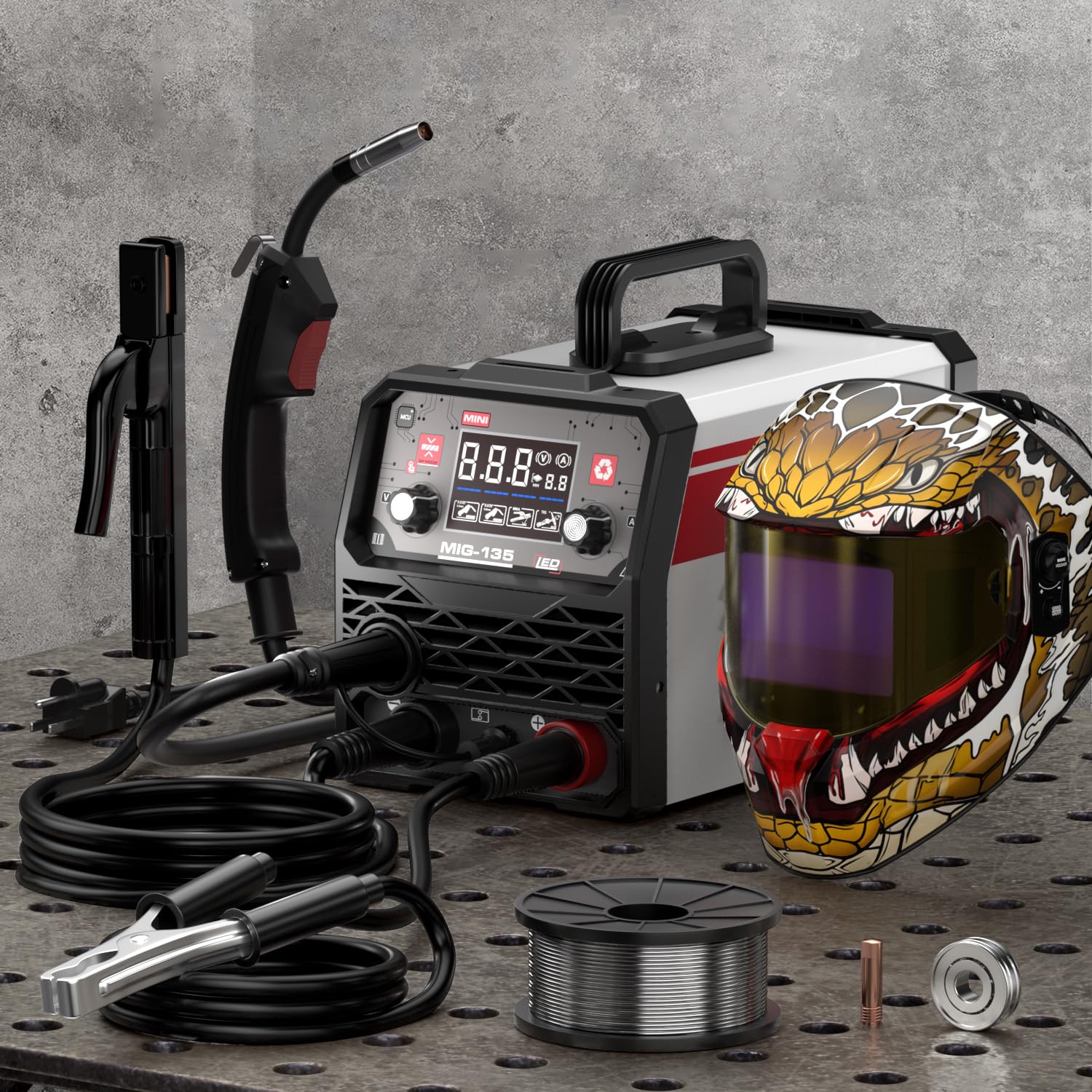
Figure 1.1: The ANDELI MIG-135MINI Multiprocess Welder. This image displays the compact design of the welding machine, highlighting its portability and general appearance.
2. Safety Instructions
Welding can be dangerous if proper safety precautions are not observed. Always prioritize safety to prevent electric shock, burns, fire, and other hazards. Read and understand all safety warnings before operating the welder.
2.1 Personal Protective Equipment (PPE)
- Welding Helmet: Always wear a welding helmet with appropriate shade filter to protect eyes and face from arc rays and sparks.
- Welding Gloves: Use heavy, flame-resistant welding gloves to protect hands from heat, sparks, and electric shock.
- Protective Clothing: Wear flame-resistant clothing, long sleeves, and pants to protect skin from sparks and UV radiation. Avoid synthetic fabrics.
- Safety Footwear: Wear sturdy, closed-toe shoes, preferably leather, to protect feet from falling objects and sparks.
2.2 Electrical Safety
- Ensure the welder is properly grounded.
- Never operate the welder in wet conditions or damp environments.
- Inspect all cables and connections for damage before each use. Replace damaged components immediately.
- Do not touch live electrical parts.
2.3 Fire and Explosion Prevention
- Remove all flammable materials from the welding area.
- Have a fire extinguisher readily available.
- Do not weld on containers that have held flammable materials.
2.4 Fume and Gas Safety
- Ensure adequate ventilation in the welding area to avoid inhaling welding fumes.
- If ventilation is poor, use an approved respirator.
3. Product Overview
Familiarize yourself with the components of your ANDELI MIG-135MINI welder before operation.
3.1 Front Panel

Figure 3.1: Front Control Panel. This image illustrates the layout of the control panel, including mode selection, current/voltage adjustment knobs, and display screen.
- Mode Selection Switch: Selects between MIG, Lift TIG, and MMA welding modes.
- Current/Voltage Adjustment Knob: Adjusts welding current (MMA/TIG) or voltage (MIG).
- Wire Speed Adjustment Knob (MIG Mode): Adjusts the speed of the welding wire feed.
- Digital Display: Shows current, voltage, or wire speed settings.
- Output Terminals: Connections for welding torch, electrode holder, and ground clamp.
3.2 Rear Panel
- Power Input: Connects to 110V AC power supply.
- Power Switch: Turns the welder ON/OFF.
- Cooling Fan: Provides necessary cooling for internal components.
3.3 Internal Wire Feeder

Figure 3.2: Internal Wire Feeder Assembly. This image shows the mechanism for loading and feeding welding wire, including the wire spool holder and drive rollers.
The welder features an integrated wire feeder for MIG welding, designed for smooth and consistent wire delivery.
4. Setup
Proper setup is crucial for safe and effective welding.
4.1 Unpacking and Inspection
- Carefully remove the welder and all accessories from the packaging.
- Inspect the machine for any signs of shipping damage. If damage is found, contact your dealer immediately.
- Verify that all components listed in the packing list are present.
4.2 Power Connection
- The ANDELI MIG-135MINI operates on a 110V AC power supply.
- Connect the power cord to a dedicated 110V, 20A (minimum) grounded outlet.
- Ensure the power switch on the rear panel is in the "OFF" position before connecting to power.
4.3 Wire Installation (MIG Flux-Cored)

Figure 4.1: Welder Setup Diagram. This diagram illustrates the connections for the welding torch, ground clamp, and power, along with the wire spool installation.
- Open the wire feeder compartment.
- Place the 0.030 inch (1kg) flux-cored welding wire spool onto the spool holder. Ensure it rotates freely.
- Thread the wire through the guide tube and into the drive rollers.
- Close the drive roller tension arm and adjust the tension. It should be tight enough to feed the wire without slipping, but not so tight as to deform the wire.
- Ensure the correct drive roller groove (0.030 inch) is aligned with the wire.
- Feed the wire through the MIG torch liner until it exits the contact tip. You may need to press the torch trigger with the power on (but no arc) to advance the wire.
4.4 Connecting Welding Accessories
- Ground Clamp: Connect the ground clamp cable to the appropriate output terminal on the welder (usually marked with a negative (-) symbol for flux-cored MIG). Secure the clamp to the workpiece or welding table, ensuring good electrical contact.
- MIG Torch: Connect the MIG torch cable to the positive (+) output terminal.
- MMA Electrode Holder: For MMA welding, connect the electrode holder cable to the positive (+) terminal and the ground clamp to the negative (-) terminal.
- Lift TIG Torch: For Lift TIG welding, connect the TIG torch cable to the negative (-) terminal and the ground clamp to the positive (+) terminal.
5. Operating Instructions
This section details the operation of the ANDELI MIG-135MINI in its various welding modes.
5.1 General Operation Steps
- Ensure all safety precautions are followed and PPE is worn.
- Connect the welder to power and turn the power switch ON.
- Select the desired welding mode (MIG, TIG, or MMA) using the mode selection switch.
- Adjust welding parameters (current, voltage, wire speed) according to the material thickness and welding process.
- Perform a test weld on scrap material to verify settings.
- Begin welding.
5.2 MIG Welding (Flux-Cored)
- Select "MIG" mode.
- Ensure the welder is set for flux-cored wire (no external gas required).
- Adjust voltage and wire speed. A good starting point for 0.030 inch flux-cored wire on thin steel is typically 16-18V and 150-200 IPM wire speed. Refer to a welding chart for specific material thicknesses.
- Maintain a consistent stick-out (distance from contact tip to workpiece) of about 3/8 to 1/2 inch (10-13mm).
- Use a drag technique (pulling the torch) for flux-cored welding.
5.3 Lift TIG Welding
- Select "TIG" mode.
- Connect the TIG torch to the negative (-) terminal and the ground clamp to the positive (+) terminal.
- Install a tungsten electrode (e.g., 2% Lanthanated) into the TIG torch.
- Adjust the welding current.
- To initiate the arc, gently touch the tungsten to the workpiece and then lift it slightly (approx. 1/16 inch or 1.5mm). The arc will start.
- This machine supports Lift TIG, which does not require a high-frequency start unit.
5.4 MMA (Stick) Welding
- Select "MMA" mode.
- Connect the electrode holder to the positive (+) terminal and the ground clamp to the negative (-) terminal.
- Insert the appropriate welding electrode (stick) into the electrode holder.
- Adjust the welding current based on the electrode type and diameter, and the material thickness.
- Strike the arc by lightly scratching the electrode against the workpiece, then quickly lifting it to maintain a short arc length.
6. Maintenance
Regular maintenance ensures the longevity and optimal performance of your welder.
6.1 Daily Maintenance
- Inspect all cables and connections for damage or wear.
- Clean the welding torch nozzle and contact tip (MIG) or collet/collet body (TIG) of spatter.
- Ensure the ground clamp makes good contact and is free of debris.
6.2 Weekly/Monthly Maintenance
- Clean the wire feeder assembly, removing any dust or wire shavings.
- Check the drive rollers for wear and ensure they are clean.
- Use compressed air to blow dust out of the welder's internal components through the ventilation openings. Ensure the power is disconnected before doing this.
- Inspect the power cord for any damage.
Note: For any internal repairs or complex maintenance, contact qualified service personnel. Do not attempt to repair the machine yourself if you are not trained.
7. Troubleshooting
This section provides solutions to common operational issues. For problems not listed here, contact customer support.
| Problem | Possible Cause | Solution |
|---|---|---|
| No power to the machine. | Power cord unplugged, circuit breaker tripped, power switch off. | Check power cord, reset circuit breaker, turn power switch ON. |
| No welding arc. | Poor ground connection, incorrect mode selected, wrong settings, damaged cable. | Ensure good ground contact, verify mode and settings, inspect cables. |
| Wire feeding issues (MIG). | Incorrect wire tension, clogged liner, wrong drive roller groove, spatter in contact tip. | Adjust tension, clean liner, verify drive roller, clean/replace contact tip. |
| Poor weld quality. | Incorrect settings, dirty workpiece, improper technique, wrong consumables. | Adjust settings, clean workpiece, refine technique, use correct wire/electrode. |
| Overheat protection activated. | Exceeded duty cycle, poor ventilation. | Allow machine to cool down, ensure adequate ventilation. |
8. Specifications
Technical specifications for the ANDELI MIG-135MINI Multiprocess Welder.
| Feature | Detail |
|---|---|
| Model | MIG-135MINI |
| Input Voltage | 110V AC |
| Welding Processes | MIG (Flux-Cored), Lift TIG, MMA (Stick) |
| Wire Compatibility (MIG) | 0.030 inch (1kg) Flux-Cored Wire |
| Item Weight | Approximately 18.85 pounds |
| Package Dimensions | Approximately 19.7 x 14.6 x 13.4 inches |
| Safety Features | Over-current, Over-voltage, Over-heating Automatic Protection |
9. Warranty and Support
ANDELI products are manufactured to high-quality standards. For warranty information, technical support, or service inquiries, please contact your authorized dealer or the ANDELI customer service department. Keep your purchase receipt as proof of purchase for warranty claims.
Contact information can typically be found on the ANDELI official website or through your point of purchase.


