1. Safety Information
Read all instructions carefully before installation, operation, or maintenance of the JSCC Inverter A025. Failure to follow these instructions may result in personal injury or equipment damage.
- Electrical Hazard: This device operates with high voltage. Ensure power is disconnected before performing any wiring or maintenance. Only qualified personnel should perform electrical work.
- Grounding: Properly ground the inverter to prevent electric shock.
- Environment: Install the inverter in a clean, dry, and well-ventilated area, free from corrosive gases, flammable materials, and excessive dust.
- Overload Protection: Do not exceed the rated current or power of the inverter and connected motor.
- Emergency Stop: Ensure an accessible emergency stop mechanism is in place for the connected system.
2. Product Overview
The KEYAYEYA JSCC Inverter Model A025 is a frequency converter designed for controlling the speed of AC motors. It accepts a 1-phase, 220V input and provides variable frequency output to the motor, allowing for precise speed control in various industrial applications.
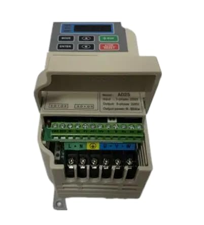
Figure 1: Front view of the KEYAYEYA JSCC Inverter A025. This image shows the compact design and typical control panel layout of the frequency converter.
This inverter is compatible with JSCC systems and offers reliable performance for motor control tasks.
3. Setup
3.1 Unpacking and Inspection
- Carefully remove the inverter from its packaging.
- Inspect the unit for any signs of physical damage during transit. If damage is found, contact your supplier immediately.
- Verify that all components listed in the packing list are present.
3.2 Mounting
Mount the inverter vertically on a stable, non-flammable surface. Ensure adequate clearance around the unit for proper ventilation and heat dissipation. Avoid mounting in direct sunlight or near heat sources.
3.3 Wiring
WARNING: Ensure power is OFF before wiring.
- Power Input (L, N): Connect the 1-phase 220V AC power supply to the designated input terminals.
- Grounding (PE): Connect the ground terminal to a reliable earth ground.
- Motor Output (U, V, W): Connect the three-phase motor leads to the inverter's output terminals. Ensure correct phase sequence if required by the motor.
- Control Terminals: Refer to the detailed wiring diagram in the complete technical manual for connecting external control signals (e.g., start/stop, speed reference, fault indicators).
Note: Use appropriate wire gauges for all connections to prevent overheating.
3.4 Initial Power-Up
- Double-check all wiring connections for correctness and security.
- Apply power to the inverter. The display should illuminate.
- Observe for any error codes or unusual behavior. If issues arise, refer to the Troubleshooting section.
4. Operating Instructions
4.1 Basic Operation
- Start: Press the RUN button on the control panel or activate the corresponding external control input.
- Stop: Press the STOP button or activate the corresponding external control input.
- Frequency Adjustment: Use the UP/DOWN arrow keys or the potentiometer (if equipped) on the control panel to adjust the output frequency, thereby controlling motor speed.
4.2 Parameter Settings
The inverter has various programmable parameters to customize its operation for specific applications (e.g., acceleration/deceleration times, motor parameters, control modes). Accessing and modifying these parameters typically involves navigating through the control panel menu.
Refer to the comprehensive programming manual for detailed instructions on parameter settings. Incorrect parameter settings can lead to improper operation or damage.
5. Maintenance
5.1 Regular Inspection
- Periodically check for loose connections, damaged wiring, or abnormal noises/vibrations.
- Inspect cooling fans for proper operation and ensure air vents are not obstructed.
- Check for signs of overheating or discoloration on components.
5.2 Cleaning
WARNING: Disconnect power before cleaning.
- Use a soft, dry cloth to wipe the exterior of the inverter.
- For internal cleaning (if necessary), use compressed air to remove dust from heat sinks and circuit boards. Avoid using liquids or solvents.
5.3 Storage
If storing the inverter for an extended period, ensure it is kept in a dry, dust-free environment within the specified temperature and humidity ranges.
6. Troubleshooting
This section provides general guidance for common issues. For detailed error codes and advanced troubleshooting, consult the full technical manual.
| Problem | Possible Cause | Solution |
|---|---|---|
| Inverter does not power on | No input power; Blown fuse; Loose wiring | Check power supply; Inspect/replace fuse; Verify all connections |
| Motor does not run | Incorrect wiring; Motor parameters not set; Emergency stop active; Overload | Check motor wiring; Configure motor parameters; Release E-stop; Reduce load |
| Overcurrent/Overload fault | Motor overloaded; Short circuit in motor/wiring; Incorrect acceleration time | Reduce load; Check motor/wiring; Increase acceleration time parameter |
| Overvoltage/Undervoltage fault | Input voltage fluctuation; Incorrect deceleration time | Check input power supply; Increase deceleration time parameter |
If the problem persists after attempting these solutions, contact technical support.
7. Specifications
| Feature | Detail |
|---|---|
| Model | A025 |
| Input Voltage | 1-Phase 220V |
| Compatible with | JSCC Inverter Systems |
| Package Dimensions | 1 x 1 x 1 inches |
| Item Weight | 4.4 pounds |
| Manufacturer | Original Manufacturer |
8. Warranty and Support
This product is covered by a one-year limited warranty from the date of purchase. This warranty covers manufacturing defects under normal use conditions.
For any questions regarding your model, technical assistance, or warranty claims, please contact the seller directly. Provide your purchase details and model number (A025) for efficient support.
Contact information for the seller can typically be found on your purchase receipt or the platform where the product was acquired.