1. Introduction
Thank you for choosing the OLZFJAJE EACT-4P-100 Household AC Contactor. This device is designed for controlling electrical loads in residential and light commercial applications, offering reliable switching capabilities. It features a compact, modular design and is built with high-performance insulation materials to ensure operational safety. This manual provides essential information for the safe and efficient installation, operation, and maintenance of your AC contactor.
2. Safety Information
Please read and understand all safety instructions before installing or operating this product. Failure to follow these instructions may result in electric shock, fire, or serious injury.
- Installation and maintenance should only be performed by qualified personnel.
- Always disconnect power before working on the contactor or associated wiring.
- Ensure proper grounding and wiring according to local electrical codes and standards.
- Do not operate the contactor if it is damaged or if any parts are missing.
- Verify that the voltage and current ratings of the contactor match your application requirements.
3. Product Overview
The EACT-4P-100 is a modular AC contactor designed for DIN rail mounting. It is available in various contact configurations (4NO, 4NC, 2NO2NC, 3NO1NC) to suit different control needs. Its compact design and quiet operation make it suitable for diverse applications.
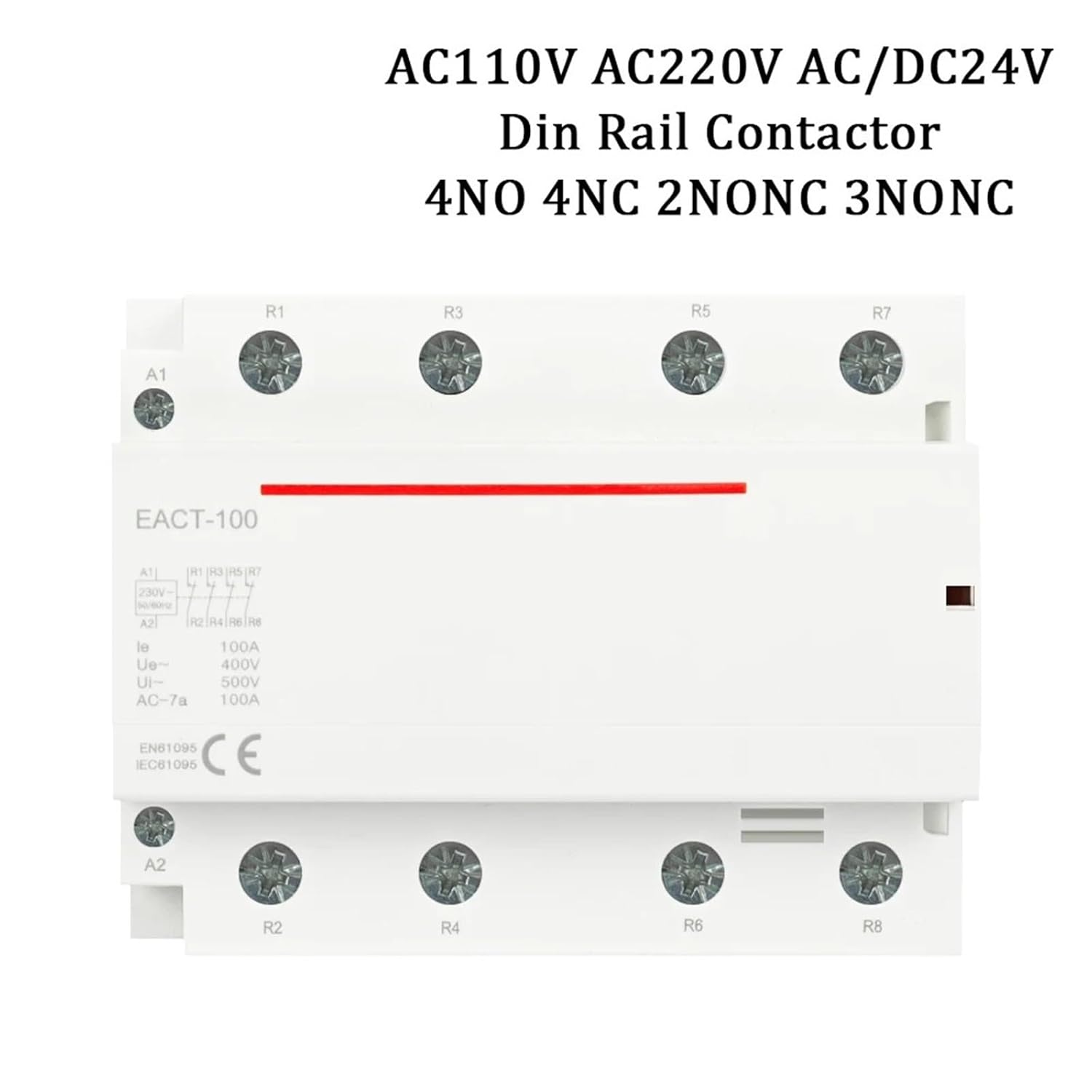
Figure 3.1: Front view of the EACT-4P-100 AC Contactor, showing terminals A1, A2, R1-R8, and product labeling.

Figure 3.2: Dimensions of the EACT-4P-100 AC Contactor (110mm x 87mm x 69mm) and a table of key product parameters.
4. Specifications
| Parameter | Value |
|---|---|
| Model Number | EACT-4P-100 |
| Current Rating | 100A |
| Main Circuit Rating Voltage | 230V AC (also supports 220V AC, DC24V) |
| Voltage Rating (Ue) | 400VAC |
| Insulation Voltage (Ui) | 500VAC |
| Frequency | 50/60Hz |
| Utilization Category | AC-1, AC-7a, AC-7b |
| Standard | IEC / EN 61095 |
| Electrical Endurance | 100,000 cycles |
| Operating Temperature | -5°C to +60°C |
| Storage Temperature | -40°C to +70°C |
| Pollution Degree | 2 |
| Degree of Protection | IP20 (IEC 60529) |
| Rated Impulse Withstand Voltage (Uimp) | 2.5kV (4 kV for 12/24/48VAC) |
| Contact Configurations | 4NO, 4NC, 2NO2NC, 3NO1NC |
| Item Weight | 1.76 ounces |
| Package Dimensions | 0.39 x 0.39 x 0.39 inches |
5. Installation and Wiring
The EACT-4P-100 contactor is designed for DIN rail mounting. Ensure the mounting surface is stable and free from vibrations. Follow the wiring diagrams carefully for correct installation.
5.1 General Wiring Principles
- Connect the control voltage to terminals A1 and A2 to energize the coil.
- The main circuit connections are made to terminals R1-R8, depending on the contact configuration.
- Always use appropriate wire gauges for the current rating to prevent overheating.
- Ensure all connections are tight and secure.
5.2 2NO Wiring Schematic
This diagram illustrates the wiring for a 2 Normally Open (2NO) contactor configuration. When coils A1 and A2 are energized, the load connected to the NO contacts is also energized.
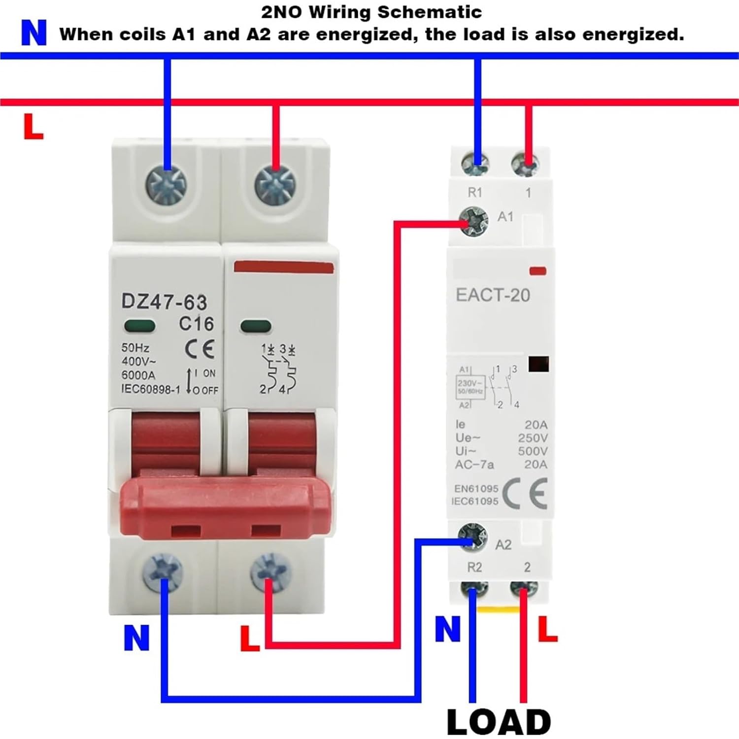
Figure 5.1: Wiring diagram for a 2NO contactor configuration, showing connections from a circuit breaker (DZ47-63 C16) to the EACT-20 (example model) contactor's A1/A2 coil and R1/R2 load terminals.
5.3 1NO1NC Wiring Schematic
This diagram shows the wiring for a 1 Normally Open (1NO) and 1 Normally Closed (1NC) contactor configuration. When coils A1 and A2 are energized, Load 1 (connected to NO) is energized, and Load 2 (connected to NC) is de-energized.

Figure 5.2: Wiring diagram for a 1NO1NC contactor configuration, illustrating connections from a circuit breaker to the contactor's coil and separate loads for NO and NC contacts.
6. Operation
The EACT-4P-100 AC Contactor operates by energizing its coil (A1-A2 terminals). When the coil is energized with the specified control voltage (e.g., 24V DC, 110V AC, 220V AC), the magnetic field generated pulls the armature, causing the main contacts to change state. Normally Open (NO) contacts will close, and Normally Closed (NC) contacts will open, thereby controlling the connected electrical load.
- Energizing the Coil: Apply the rated control voltage to terminals A1 and A2. The contactor will audibly click as the contacts engage.
- De-energizing the Coil: Remove the control voltage from A1 and A2. The contactor will disengage, and the contacts will return to their original state.
- Indicator: Some models may include a visual indicator to show the contactor's state (energized/de-energized).
7. Maintenance
The EACT-4P-100 contactor is designed for long-term, reliable operation with minimal maintenance. However, periodic checks can help ensure optimal performance and safety.
- Visual Inspection: Regularly inspect the contactor for any signs of physical damage, discoloration, or loose connections.
- Terminal Tightness: Periodically check that all terminal screws are securely tightened to prevent overheating due to poor contact.
- Cleanliness: Ensure the contactor is free from dust, dirt, and moisture. Use a dry, soft cloth for cleaning. Do not use solvents.
- Operational Check: If possible and safe to do so, periodically test the contactor's switching action to ensure it engages and disengages smoothly.
8. Troubleshooting
If you encounter issues with your EACT-4P-100 AC Contactor, refer to the following troubleshooting guide. Always disconnect power before attempting any inspection or repair.
| Problem | Possible Cause | Solution |
|---|---|---|
| Contactor does not energize (no click) |
|
|
| Contactor energizes but load does not receive power |
|
|
| Contactor hums loudly or chatters |
|
|
9. Warranty and Support
For warranty information or technical support, please refer to the product packaging or contact your retailer. Keep your purchase receipt as proof of purchase. For any questions regarding installation or operation not covered in this manual, please reach out to OLZFJAJE customer service or a qualified electrician.