1. Introduction
This manual provides detailed instructions for the installation, operation, and maintenance of the Waveshare Modbus POE ETH Relay (B) 8-Channel Ethernet Relay Module. This industrial-grade module features 8 relay channels, digital inputs, and supports Modbus RTU/TCP protocols over Ethernet, including Power over Ethernet (PoE) functionality. It is designed for various control applications requiring reliable and isolated switching.

Figure 1: Waveshare Modbus POE ETH Relay (B) Module
2. Key Features
- 8-Channel Relay Output: Supports up to 10A 250VAC/30VDC contact rating.
- Digital Input: Passive (dry contact) and active (wet contact) digital inputs with bi-directional optocoupler isolation.
- Communication: Ethernet port supporting Modbus RTU/TCP, MQTT, TCP Server/Client, UDP Mode/Multicast, HTTP.
- Power Supply: DC 7-36V wide range input and IEEE 802.3af compliant PoE.
- Protection: Optocoupler isolation, flyback diode protection, reverse-proof circuit.
- Enclosure: Rail-mounted ABS plastic for easy installation.
- Indicators: LEDs for MCU status, network activity, and signal transceiving.
3. Product Components and Interfaces
The module features various ports and indicators for power, network, relay outputs, and digital inputs. Understanding these components is crucial for proper setup and operation.
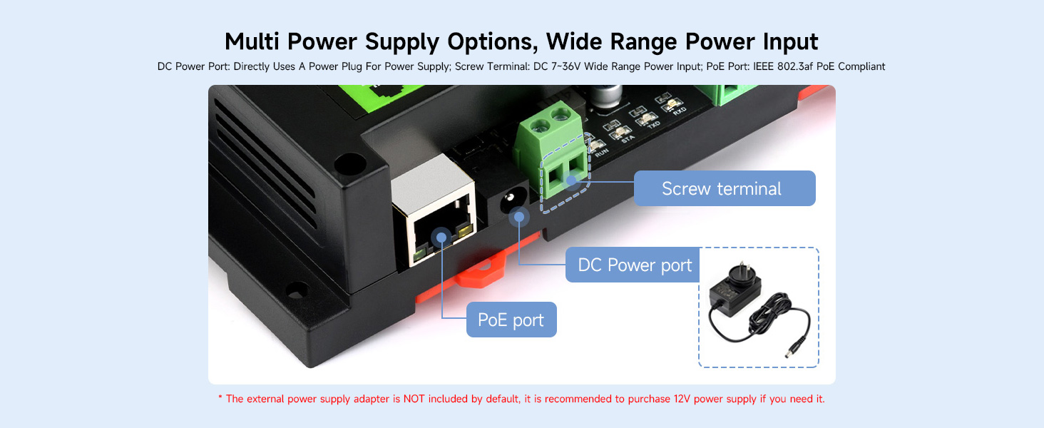
Figure 2: Power Supply Options (PoE Port, DC Power Port, Screw Terminal)
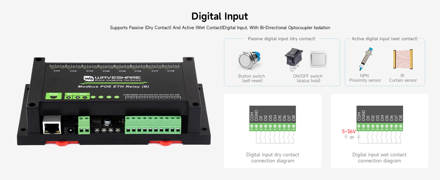
Figure 3: Digital Input and Relay Output Terminals
4. Installation and Setup
Follow these steps to properly install and set up your relay module.
4.1 Power Connection
The module supports two power input methods:
- DC Power Input: Connect a DC 7-36V power supply to the screw terminal or DC power jack. Ensure correct polarity.
- PoE (Power over Ethernet): If using a PoE-enabled network switch or injector, connect an Ethernet cable to the PoE port. The module will draw power directly from the Ethernet cable.
Note: An external power supply adapter is not included. A 12V power supply is recommended if not using PoE.
4.2 Network Connection
Connect the module to your network using a standard Ethernet cable plugged into the RJ45 port. The module supports various communication protocols for control.
4.3 Mounting
The module features a rail-mounted ABS plastic enclosure for easy installation onto standard DIN rails in industrial control cabinets.
5. Wiring Diagrams
Proper wiring is essential for safe and effective operation. Refer to the diagrams below for relay and digital input connections.
5.1 Relay Connection
The relays can control both AC and DC devices. Each relay has Normally Open (NO) and Common (COM) terminals. Ensure the load's voltage and current do not exceed the relay's contact rating (≤10A 250VAC/30VDC).
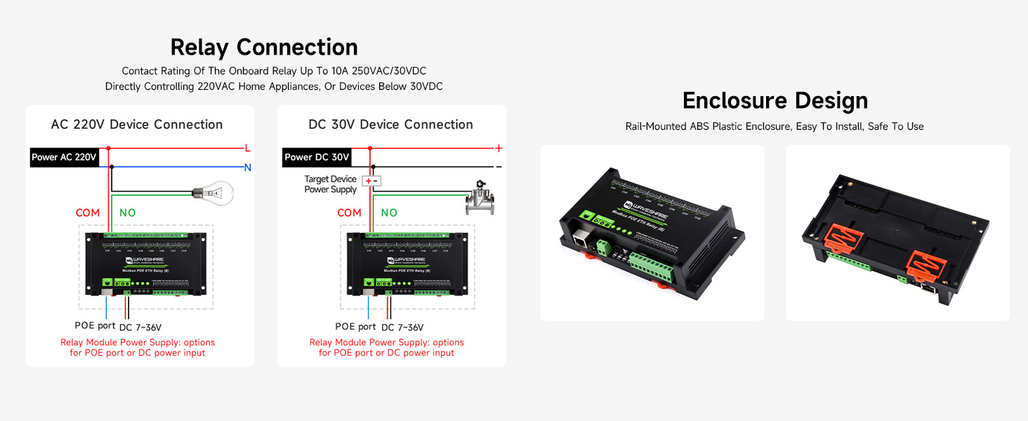
Figure 4: AC and DC Relay Connection Diagrams
5.2 Digital Input Connection
The module supports both passive (dry contact) and active (wet contact) digital inputs. Bi-directional optocoupler isolation protects the module from external interference.
Figure 5: Digital Input Connection Diagrams
6. Operation Modes
The module offers multiple relay control modes to suit various automation scenarios. Each channel can be configured independently.
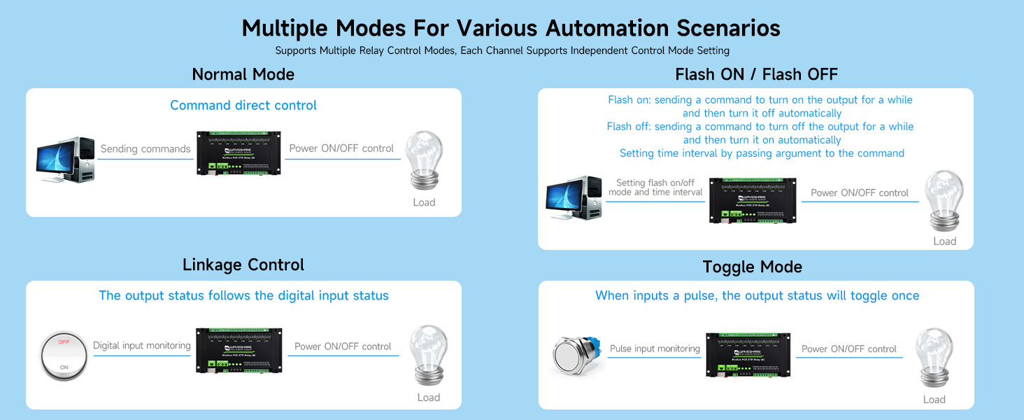
Figure 6: Multiple Relay Control Modes
- Normal Mode (Command Direct Control): Relays are controlled directly by sending commands.
- Flash ON / Flash OFF: Allows turning a relay ON for a specified duration and then automatically turning it OFF, or vice-versa. The duration is set via command arguments.
- Linkage Control: The relay output status follows the state of a corresponding digital input.
- Toggle Mode: When a pulse is detected on the digital input, the relay output status will toggle (ON to OFF, or OFF to ON).
7. Communication and Configuration
The module supports various communication protocols and can be configured via software or a web browser.
7.1 Supported Protocols
The module supports:
- Modbus RTU/TCP Protocol
- MQTT Protocol (with Alibaba Cloud MQTT application demo support)
- TCP Server/Client
- UDP Mode/Multicast
- HTTP
7.2 Configuration Methods
The module's network parameters and relay settings can be configured using dedicated software tools or through a web browser interface. Dynamic IP via DHCP is supported, and domain name server resolution via DNS protocol is available.
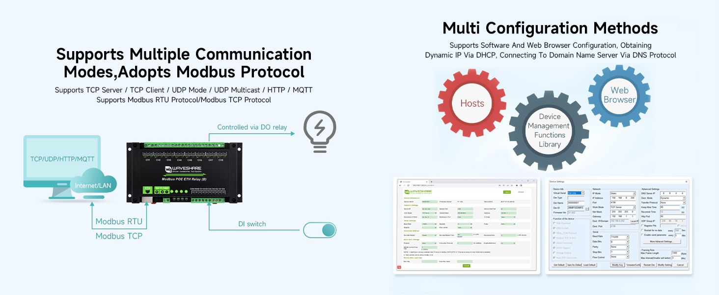
Figure 7: Configuration Interface Examples
8. Indicators
The module is equipped with several LED indicators to monitor its status and network activity.

Figure 8: Module Indicators
| Indicator | Description |
|---|---|
| RUN | MCU status indicator, blinks when the MCU is operating normally. |
| STA | Ethernet port indicator, blinks when the Ethernet port is working normally. |
| TXD | Transmit Data indicator, lights up when sending data. |
| RXD | Receive Data indicator, lights up when receiving data. |
| Ethernet Port Green | Lights up when the network connection is established. |
| Ethernet Port Yellow | Data activity indicator, blinks when transmitting data. |
| CH1-CH8 LEDs | Indicates the ON/OFF status of the corresponding relay channel. |
9. Specifications
| Feature | Specification |
|---|---|
| Model Number | Modbus POE ETH Relay (B) |
| Relay Channels | 8 |
| Contact Rating | ≤10A 250VAC / 30VDC |
| Power Input | DC 7-36V (screw terminal/DC jack) or PoE (IEEE 802.3af compliant) |
| Digital Input | Passive (dry contact) and Active (wet contact) with optocoupler isolation |
| Communication Protocols | Modbus RTU/TCP, MQTT, TCP Server/Client, UDP, HTTP |
| Enclosure | Rail-mounted ABS plastic |
| Operating Temperature | Industrial grade (specific range not provided, but implied by 'industrial grade') |
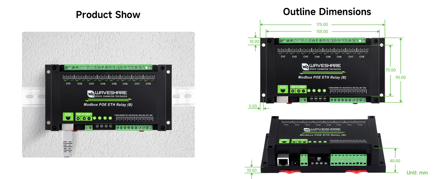
Figure 9: Outline Dimensions (Unit: mm)
10. Troubleshooting
If you encounter issues with your module, refer to the following common troubleshooting steps:
- No Power: Check the power supply connection (DC 7-36V or PoE). Ensure the power source is active and within the specified voltage range. Verify the power indicator LED is on.
- No Network Connectivity: Check the Ethernet cable connection. Ensure your network switch/router is functioning. Verify the Ethernet port green and yellow LEDs are active.
- Relay Not Activating: Confirm the control command is correctly sent and received (check TXD/RXD LEDs). Verify the relay channel LED. Ensure the load is properly wired and within the contact rating.
- Digital Input Not Responding: Check the wiring of the digital input. Ensure the input signal is within the module's specifications for passive or active inputs.
- Module Unresponsive: Try power cycling the module. If issues persist, consult the manufacturer's support resources.
11. Maintenance
The Waveshare Modbus POE ETH Relay (B) module is designed for robust operation with minimal maintenance. To ensure longevity and reliable performance:
- Keep the module in a clean, dry environment, free from excessive dust and moisture.
- Ensure proper ventilation to prevent overheating, especially in enclosed spaces.
- Periodically check all wiring connections for tightness and integrity.
- Avoid exposing the module to extreme temperatures or corrosive substances.
12. Warranty and Support
This Waveshare product comes with a 1-year warranty from the date of purchase, covering manufacturing defects. For technical support, detailed documentation, or warranty claims, please visit the official Waveshare website or contact their customer service directly. Provide your product model number and purchase details when seeking support.