1. Introduction
This document provides instructions for the ACE4U 6.2KW Hybrid Solar Inverter. This multi-function inverter/charger integrates an inverter, solar charger, and battery charger to deliver uninterrupted power. It features a comprehensive LCD display for user-configurable settings such as battery charging current, AC/solar charger priority, and acceptable input voltage for various applications.
The solar charging module utilizes optimized MPPT technology to efficiently track the maximum power point of the PV array, maximizing energy harvest from solar panels and converting DC to pure sine wave AC output.
2. Key Features
- Pure sine wave output.
- Configurable input voltage range for appliances and computers via LCD.
- Adjustable battery charging current via LCD.
- Configurable AC/Solar Charger priority via LCD.
- Compatible with mains voltage or generator power.
- Automatic restart upon AC recovery.
- Overload, over temperature, and short circuit protection.
- Smart battery charger design for optimized battery performance.
- Cold start function.
3. Product Overview
3.1 Main Features and Specifications

Image 1: Front view of the ACE4U 6.2KW Hybrid Solar Inverter highlighting its main features including 6.2KW 48V 230VAC, 120A Max Solar Charge Current, 6200W Rated Power, 500VDC High PV Input, and WIFI support.
3.2 Component Identification

Image 2: Detailed view of the inverter's components and ports. Key components include: 1. LCD Display, 2. Status indicator, 3. Charging indicator, 4. Fault indicator, 5. Function buttons, 6. Power on/off switch, 7. AC Input, 8. AC Output, 9. PV Input, 10. Battery Input, 11. Circuit breaker, 12. RS-232 communication port/WIFI port, 13. Anti dust kit (Optional).
3.3 Rear Panel Connections
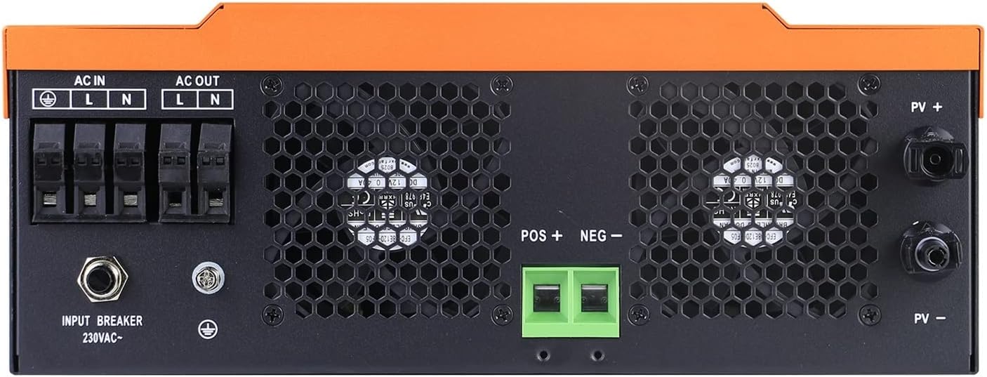
Image 3: Close-up of the inverter's rear panel showing AC input, AC output, PV input terminals (PV+ and PV-), and battery input terminals (POS+ and NEG-). Also visible are the input breaker and grounding screw.
4. System Connection Diagram

Image 4: Diagram illustrating the typical connection of the hybrid solar inverter within a power system. It shows connections from solar modules (sunlight), utility grid, and a generator to the inverter. The inverter then connects to the utility grid, home appliances, and supports both lead-acid and lithium batteries for charging and discharging.
5. Setup and Installation
Installation of this hybrid solar inverter should be performed by qualified personnel in accordance with all local and national electrical codes. Ensure the installation site is well-ventilated, dry, and protected from direct sunlight and moisture.
5.1 Mounting
- Mount the inverter vertically on a sturdy surface.
- Ensure adequate clearance around the unit for proper heat dissipation.
5.2 Wiring Connections
- Battery Connection: Connect the battery bank to the inverter's battery terminals (POS+ and NEG-). Ensure correct polarity.
- PV Input Connection: Connect the solar panel array to the PV input terminals (PV+ and PV-). Verify correct polarity and voltage within the specified range.
- AC Input Connection: Connect the utility grid or generator AC supply to the AC input terminals (L, N, Ground).
- AC Output Connection: Connect your loads (home appliances) to the AC output terminals (L, N, Ground).
- Grounding: Ensure the inverter is properly grounded.
Warning: Incorrect wiring can cause damage to the inverter, batteries, and connected loads, and poses a risk of electric shock. Always consult the detailed wiring diagrams in the full product manual and adhere to safety guidelines.
6. Operation
6.1 Power On/Off
- Ensure all wiring connections are secure.
- Turn on the battery breaker first.
- Turn on the PV array breaker (if applicable).
- Press the Power On/Off switch (6) on the inverter.
- The LCD display (1) will illuminate, and the status indicator (2) will show the operational status.
6.2 LCD Display and Function Buttons
The LCD display provides real-time operational data and allows for configuration of various settings. Use the function buttons (5) to navigate menus and adjust parameters.
6.3 Working Modes and LED Indicators

Image 5: This image illustrates the LED light patterns (RGB) indicating different working modes of the inverter. The logo light changes color to signify the current operational state: Stationary mode, PV Mode (Purple Light), Utility Mode (Blue Light), and Battery Mode (Red Light).
The inverter's logo light provides a quick visual indication of its current working mode:
- Stationary Mode: Default or standby state.
- PV Mode (Purple Light): Inverter is primarily drawing power from the PV array.
- Utility Mode (Blue Light): Inverter is primarily drawing power from the utility grid.
- Battery Mode (Red Light): Inverter is primarily drawing power from the battery bank.
7. Maintenance
Regular maintenance ensures optimal performance and longevity of your inverter.
- Cleaning: Keep the inverter's exterior clean and free from dust. Ensure ventilation openings are not obstructed.
- Connections: Periodically check all electrical connections for tightness and signs of corrosion.
- Environment: Ensure the operating environment remains within specified temperature and humidity ranges.
- Battery Health: Monitor battery voltage and health according to battery manufacturer guidelines.
Caution: Disconnect all power sources (PV, AC, Battery) before performing any maintenance or cleaning.
8. Troubleshooting
This section provides guidance for common issues. For complex problems, contact technical support.
- No Power Output: Check AC input, battery connections, and ensure the inverter is powered on. Verify circuit breakers are not tripped.
- No Charging: Check PV input voltage and current. Ensure solar panels are clean and receiving adequate sunlight. Verify battery connections.
- Fault Indicator On: Refer to the inverter's LCD display for specific error codes. Common faults include overload, over temperature, or short circuit. Address the cause and restart the inverter.
- Inverter Shutting Down: This could be due to overload, low battery voltage, or over temperature. Reduce load, check battery charge, or ensure proper ventilation.
9. Specifications
| Feature | Specification |
|---|---|
| Phase | 1-phase |
| Maximum PV Input Power | 6200W |
| Rated Output Power | 6200W |
| Maximum Charging Power | 6200W |
| Nominal DC Voltage (PV) | 360VDC |
| Maximum DC Voltage (PV) | 500VDC |
| MPPT Voltage Range | 120VDC~450VDC |
| Nominal Output Voltage (GRID) | 220/230VAC |
| Output Voltage Range (GRID) | 195.5-253VAC |
| Nominal Output Current (GRID) | 26.1A |
| Power Factor | >0.9 |
| Maximum Conversion Efficiency (DC/AC) | 97% |
| AC Start-up Voltage | 120-140VAC |
| Auto Restart Voltage (AC) | 180VAC |
| Acceptable Input Voltage Range (AC) | 90-280VAC OR 170-280VAC |
| Nominal DC Voltage (Battery Mode Output) | 48VDC |
| Output Waveform (Battery Mode) | Pure sine wave |
| Efficiency (DC to AC) | 94% |
| Dimensions (D*W*H) | 420*310*120 mm |
| Net Weight | 11.5 kgs (25.35 lbs) |
| Communication Port | RS232/WIFI |
| Humidity | 0-90% (Non-condensing) |
| Item Model Number | 1005004181438685 |
| Item Weight | 28.7 pounds |
| Package Dimensions | 13.78 x 10.63 x 3.94 inches |
10. Warranty and Support
For warranty information, please refer to the terms and conditions provided at the time of purchase. For technical support or service inquiries, please contact your vendor or the manufacturer directly. Ensure you have your model number and purchase details available.