UNCLE BRICK up2512-1
UNCLE BRICK 12-in-1 Motor Power Function Set
Model: up2512-1
Introduction
This instruction manual provides detailed guidance for the UNCLE BRICK 12-in-1 Motor Power Function Set. This set is designed to enhance building block creations by adding dynamic movement and control. It includes a variety of motors, power sources, and control components, compatible with UNCLE BRICK products and other major building block brands. Unleash your creativity by transforming static models into interactive, motorized structures.
Safety Information
Warning: Choking Hazard - Small Parts. Not suitable for children under 3 years old. Adult supervision is recommended for children under 8 years old.
Package Contents
The UNCLE BRICK 12-in-1 Motor Power Function Set includes the following components:
- 1x Speed Control Remote Control (requires 3 AAA batteries, not included)
- 1x Power Supply Box (requires 6 AA batteries, not included)
- 1x AAA Battery Box (requires 6 AAA batteries, not included)
- 1x Receiver
- 1x Transfer Switch
- 1x XL Motor
- 1x M Motor
- 1x L Motor
- 1x Servo Motor
- 1x Train Motor
- 1x Extension Cord
- 1x LED Light Module

Image: Overview of all components included in the UNCLE BRICK 12-in-1 Motor Power Function Set, showing the remote control, battery boxes, various motors, and connecting cables.
Setup
1. Battery Installation
Ensure all batteries are installed correctly before use. Use new, high-quality batteries for optimal performance.
- Speed Control Remote Control: Open the battery compartment on the back of the remote control. Insert 3 AAA batteries, observing the correct polarity (+/-). Close the compartment securely.
- Power Supply Box (AA): Open the battery compartment. Insert 6 AA batteries, observing the correct polarity (+/-). Close the compartment securely.
- AAA Battery Box: Open the battery compartment. Insert 6 AAA batteries, observing the correct polarity (+/-). Close the compartment securely.
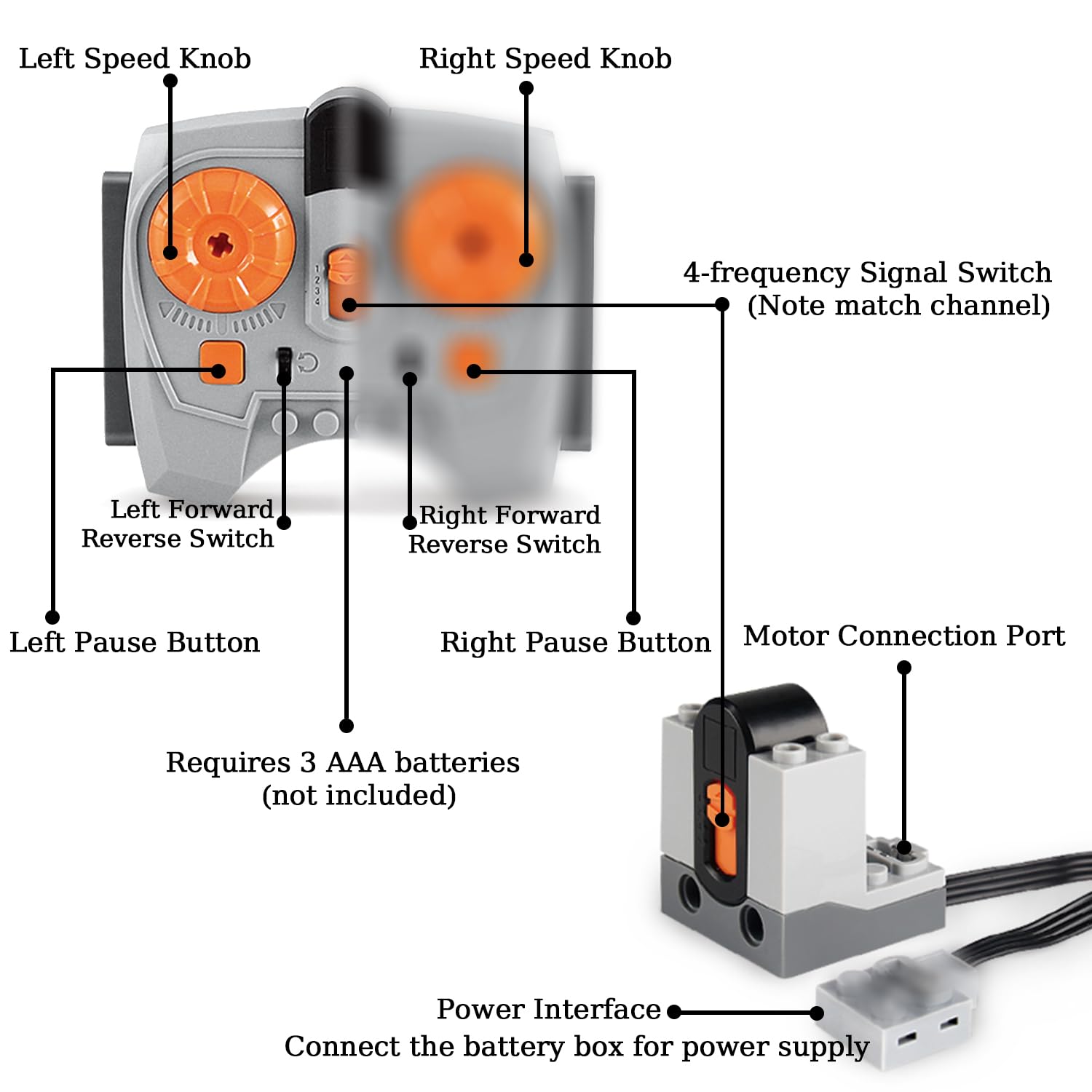
Image: Diagram illustrating the features of the speed control remote control, including left/right speed knobs, forward/reverse switches, pause buttons, 4-frequency signal switch, and motor connection port. It also indicates the requirement for 3 AAA batteries.
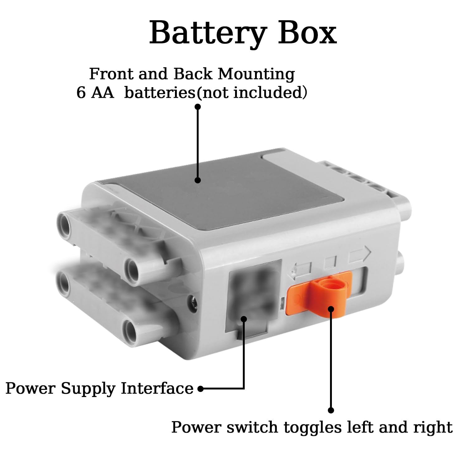
Image: Diagram of the main power supply box, showing the front and back mounting points, the power supply interface, and the power switch. It specifies the use of 6 AA batteries.
2. Component Connection
Connect motors and other components to the receiver or power supply boxes using the provided power cords and extension cord. Ensure connections are firm.
- Motors: Each motor (XL, M, L, Servo, Train) has a power cord and a power interface. Connect these to the receiver or directly to a battery box if using the transfer switch.
- Receiver: The receiver connects to a power supply box and then to motors. It allows for remote control operation.
- Transfer Switch: This switch can be used to control a motor or LED light module directly, providing on/off and direction control without the remote.
- Extension Cord: Use the extension cord to extend the reach of motors or other components when needed.

Image: Close-up diagram of a motor, highlighting the power cord, power interface, motor shaft connector, and mounting interface for integration with building blocks.
Operating Instructions
1. Remote Control Operation
The speed control remote allows for precise control of connected motors.
- Power On: Ensure batteries are installed in the remote and the connected power supply box. Turn on the power supply box.
- Frequency Switch: Match the 4-frequency signal switch on the remote to the receiver's channel for proper communication.
- Speed Knobs: Use the Left and Right Speed Knobs to adjust the rotational speed of the motors connected to the corresponding channels.
- Forward/Reverse Switches: The Left and Right Forward/Reverse Switches control the direction of rotation for motors on their respective channels.
- Pause Buttons: Press the Left or Right Pause Button to temporarily stop the motor's operation on that channel.
2. Transfer Switch Usage
The transfer switch provides a simple manual control option for a single motor or the LED light module.
- Connect the transfer switch to a power supply box and then to a motor or the LED light module.
- Toggle the switch to control power (on/off) and direction (forward/reverse) for the connected component.
3. LED Light Module
The LED light module can be integrated into your building block creations to add illumination.
- Connect the LED light module to a power supply box or through the transfer switch.
- Ensure proper connection for the light to function.
Maintenance
To ensure the longevity and optimal performance of your UNCLE BRICK Motor Power Function Set, follow these maintenance guidelines:
- Cleaning: Wipe components with a dry, soft cloth. Avoid using water or cleaning solutions, as they can damage electronic parts.
- Storage: Store the set in a cool, dry place away from direct sunlight and extreme temperatures.
- Battery Care: Remove batteries from the remote control and battery boxes if the set will not be used for an extended period to prevent leakage and damage.
- Handling: Handle all components with care to avoid physical damage to wires, connectors, and motor housings.
Troubleshooting
If you encounter issues with your UNCLE BRICK Motor Power Function Set, refer to the following common problems and solutions:
- Problem: Motors are not responding to the remote control.
Solution:- Check if batteries are correctly installed in both the remote control and the power supply box, and if they have sufficient charge.
- Ensure the power supply box is switched ON.
- Verify that the 4-frequency signal switch on the remote control matches the channel of the receiver.
- Confirm that all connections between the power supply, receiver, and motors are secure.
- Problem: Motor runs slowly or inconsistently.
Solution:- Replace old batteries with new ones. Low battery power can affect motor performance.
- Check for any obstructions or excessive friction in the building block assembly that might be hindering motor movement.
- Ensure the motor is not overloaded beyond its capacity.
- Problem: LED light module does not illuminate.
Solution:- Check battery levels in the connected power supply.
- Verify all connections to the power source are secure.
- If using a transfer switch, ensure it is in the 'on' position.
Specifications
| Feature | Detail |
|---|---|
| Product Dimensions | 10.6 x 7 x 1.9 inches |
| Product Weight | 1.21 Pounds |
| Manufacturer Recommended Age | 8 - 12 years |
| Model Name | up2512-1 |
| Motor Speed | 580 RPM |
| Voltage | 7400 Millivolts |
| Horsepower | 1313.95 Watts |
Support
For further assistance or inquiries regarding your UNCLE BRICK 12-in-1 Motor Power Function Set, please refer to the seller's contact information on the platform where the product was purchased. You may also visit the official UNCLE BRICK store for additional resources and product information.
Link to UNCLE BRICK Store: UNCLE BRICK Store
Related Documents - up2512-1
 |
ELCERAM OXIDE 1/8 Offroad ESC User Manual - High Power RC Racing Detailed user manual for the ELCERAM OXIDE 1/8 Offroad Electronic Speed Controller (ESC). Covers installation, setup, programming, troubleshooting, and specifications for professional 1/8 scale RC car racing with advanced cooling technology. |
 |
Quick Guide to Function and Switch Settings This document provides a quick guide to configuring function settings and switch positions for a hardware component, detailing options for RAM size, display type, system speed, drive number, and specific system configurations like 8087-1 and COM1. It also illustrates the physical switch and jumper settings. |
 |
High Torque DC Motor User Manual: Specifications and Applications Comprehensive user manual detailing the specifications, features, and applications of a high torque DC motor. Covers driving voltage, step angle, phase, and usage notes for 3D printers, CNC machines, and automation systems. |
 |
Tin Man Fabrication Custom Motor Mount Installation Guide Comprehensive installation guide for Tin Man Fabrication's custom motor mounts, detailing pre-installation checks and step-by-step mounting procedures for vehicles. |
 |
VWR Dry Block Heaters Instruction Manual: Standard and Advanced Models Comprehensive instruction manual for VWR Standard and Advanced Dry Block Heaters, covering specifications, operation, safety, troubleshooting, and replacement parts for laboratory use. |
 |
Chronos 4K12 User Manual: High-Speed Imaging Guide by Kron Technologies Explore the capabilities of the Kron Technologies Chronos 4K12 high-speed camera with this comprehensive user manual. Learn about setup, operation, recording, playback, and advanced features for professional slow-motion video production. |
Ask a question about this manual
Ask about setup, troubleshooting, compatibility, parts, safety, or missing instructions. Manuals+ will review the question and use this page’s manual context to help answer it.