1. Introduction
This manual provides essential information for the safe and efficient installation, operation, and maintenance of the Schneider Electric Altivar Process ATV900 Series Variable Speed Drive, model ATV950D15N4EU. This drive is designed for industrial applications requiring precise motor control and energy efficiency. Please read this manual thoroughly before attempting any procedures to ensure proper handling and to prevent personal injury or equipment damage.
2. Safety Information
WARNING: Electrical shock hazard. Only qualified personnel should install, operate, or service this equipment. Disconnect all power before working on the drive.
This product complies with various international safety standards, including EN/IEC 61800-3 (Environment 1 category C2, Environment 2 category C3), EN/IEC 61800-5-1, IEC 61000-3-12, IEC 60721-3, IEC 61508, and IEC 13849-1. Certifications include ATEX, INERIS, TUV, UL, Bureau Veritas CSA, DNV-GL, ABS CE.
- Always follow local and national electrical codes.
- Ensure proper grounding of the drive and motor.
- Do not operate the drive with damaged components.
- Wear appropriate personal protective equipment (PPE).
- Refer to the California Proposition 65 Warning for potential chemical exposures.
3. Product Overview
The Altivar Process ATV900 Series Variable Speed Drive ATV950D15N4EU is a high-performance drive designed for demanding industrial applications. It offers advanced motor control capabilities, energy efficiency, and connectivity features.
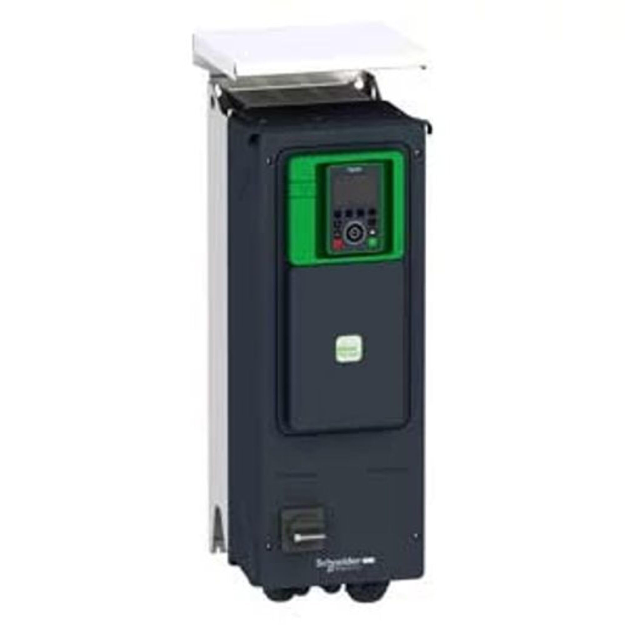
Figure 1: Front view of the Schneider Electric Altivar Process ATV900 Series Variable Speed Drive, model ATV950D15N4EU, highlighting its compact design and control panel.
Key Features:
- Rated for 15 kW (20 hp) motor applications.
- Operates on 380/480V input voltage.
- Output current of 23.3A.
- Integrated safety functions.
- Robust design for industrial environments.
4. Setup and Installation
Proper installation is crucial for the drive's performance and longevity. Ensure the installation environment meets the specified conditions (temperature, humidity, ventilation).
4.1. Mounting
- Mount the drive vertically on a flat, stable surface.
- Ensure adequate clearance for cooling air circulation (refer to the product's technical documentation for specific clearances).
- Use appropriate fasteners to secure the drive firmly.
4.2. Electrical Connections
All electrical connections must be performed by a qualified electrician.
- Power Supply Connection: Connect the main power supply (380/480V) to the designated input terminals (L1, L2, L3). Ensure correct phase sequence.
- Motor Connection: Connect the motor cables to the output terminals (U, V, W). Verify that the motor is compatible with the drive's output specifications.
- Grounding: Connect the protective earth (PE) terminal of the drive to the main grounding system.
- Control Wiring: Connect control signals (e.g., start/stop, speed reference, fault relays) to the appropriate control terminals as per your application's requirements. Refer to the wiring diagrams in the full technical manual.
5. Operating Instructions
Once installed and wired, the drive can be configured and operated.
5.1. Initial Power-Up
- Before applying power, double-check all wiring connections.
- Apply main power to the drive. The display should illuminate.
- Observe for any immediate error messages or abnormal behavior.
5.2. Basic Operation
- Parameter Setting: Use the integrated display and keypad (or a connected HMI/software) to set essential motor parameters (e.g., motor nominal power, nominal current, nominal frequency, nominal speed).
- Start/Stop: Initiate motor operation via the designated start command (e.g., digital input, fieldbus command). Stop the motor using the stop command.
- Speed Control: Adjust the motor speed using the configured speed reference source (e.g., analog input, keypad, fieldbus).
- Monitoring: Monitor drive status, motor speed, current, and other operational data on the display.
6. Maintenance
Regular maintenance ensures optimal performance and extends the lifespan of the drive.
6.1. Routine Checks
- Visual Inspection: Periodically inspect the drive for dust accumulation, loose connections, or signs of overheating.
- Cleaning: Keep the cooling fins and ventilation openings free from dust and debris. Use compressed air or a soft brush for cleaning. Ensure power is disconnected before cleaning.
- Connection Integrity: Check terminal connections for tightness, especially power connections, to prevent arcing or overheating.
6.2. Preventative Maintenance
- Fan Replacement: Cooling fans have a limited lifespan. Replace them according to the manufacturer's recommendations or if they show signs of failure.
- Capacitor Check: For drives in harsh environments, consider periodic inspection or replacement of DC bus capacitors by qualified service personnel.
7. Troubleshooting
This section provides guidance for common issues. For complex problems, contact Schneider Electric support.
7.1. Common Faults and Solutions
| Symptom/Error Code | Possible Cause | Corrective Action |
|---|---|---|
| No display/Power LED off | No input power, blown fuse, internal fault. | Check main power supply. Inspect fuses. Contact support if power is present but display is off. |
| Overcurrent Fault (OCF) | Motor overload, short circuit in motor wiring, incorrect motor parameters. | Check motor load. Inspect motor and cables for shorts. Verify motor parameters. |
| Overvoltage Fault (OVF) | High input voltage, regenerative braking without braking resistor. | Check input voltage. Install or verify braking resistor if required by application. |
| Motor does not start | No start command, incorrect control wiring, motor parameters not set. | Verify start command signal. Check control wiring. Ensure motor parameters are correctly entered. |
8. Specifications
Technical specifications for the Schneider Electric Altivar Process ATV900 Series Variable Speed Drive ATV950D15N4EU.
- Model Number: ATV950D15N4EU
- Manufacturer: Schneider Electric
- Input Voltage: 380/480V
- Output Current: 23.3A
- Motor Power: 15 kW (20 hp)
- Standards Compliance: EN/IEC 61800-3, EN/IEC 61800-5-1, IEC 61000-3-12, IEC 60721-3, IEC 61508, IEC 13849-1
- Certifications: ATEX, INERIS, TUV, UL, Bureau Veritas CSA, DNV-GL, ABS CE
- Sustainability: Green Premium product, REACh Regulation, EU RoHS Compliant, WEEE
- Date First Available: November 18, 2025
9. Warranty and Support
Schneider Electric products are backed by a manufacturer's warranty. For specific warranty terms and conditions, please refer to the documentation provided with your purchase or visit the official Schneider Electric website.
Customer Support:
For technical assistance, troubleshooting beyond this manual, or warranty claims, please contact Schneider Electric customer support through their official website or your local distributor. When contacting support, please have your product model number (ATV950D15N4EU) and serial number ready.
You can find more information and support resources by visiting the Schneider Electric Store on Amazon or their official corporate website.