1. Introduction
The Yaregelun XY-BT13L is a 30A fully automatic battery charge and discharge management module designed for bidirectional current detection. It integrates advanced protection features to safeguard your battery system. This manual provides essential information for the proper installation, operation, and maintenance of your XY-BT13L module.
2. Safety Information
Please read and understand all safety instructions before installing or operating the module. Failure to do so may result in damage to the device, battery, or personal injury.
- Ensure all power sources are disconnected before making any wiring connections.
- Verify correct polarity for all connections (positive to positive, negative to negative). Incorrect wiring can cause severe damage.
- Do not exceed the maximum current rating of 30A or the voltage range of 10-110V.
- Install the module in a well-ventilated area, away from flammable materials and moisture.
- This device is intended for use by qualified personnel or under their supervision.
3. Product Overview and Features
The XY-BT13L module offers comprehensive battery management with several key features:
- Fully Automatic Charge and Discharge Management: Prevents overcharging and under-voltage conditions.
- Bidirectional Current Detection: Monitors current flow in both charging and discharging directions.
- Advanced Protection: Includes overvoltage, undervoltage, overcurrent, low battery alarm, over-temperature protection, and delayed conduction.
- UPS Uninterruptible Power Supply Mode: Ensures continuous power during outages.
- Precision Coulometer: Provides accurate battery capacity measurement.
- Automatic Calibration: For battery capacity.
- Serial Communication: Supports standard Modbus protocol.

Figure 1: Yaregelun XY-BT13L module highlighting its main features and capabilities, including precision coulometer, overcharge/overdischarge protection, and bidirectional current detection.

Figure 2: Detailed view of the module's internal components, showing the precision external clock crystal oscillator, 10A bidirectional current sampling chip, and the 48-pin powerful MCU controller.
4. Specifications
| Parameter | Value |
|---|---|
| Product Model | XY-BT13L |
| Battery Voltage Range | 10-110V |
| Adapter Input Voltage Range | 10-110V |
| Maximum Current | 30A |
| Voltage Accuracy | ±0.5%+1 digit |
| Current Accuracy | ±0.5%+3 digits |
| Current Resolution | 0.01A |
| Voltage Resolution | 0.01V |
| Operating Temperature | -10°C to 60°C |
| Package Dimensions | 5.12 x 3.54 x 1.57 inches |
| Item Weight | 4.9 ounces |
5. Setup and Installation
Proper wiring is crucial for the safe and effective operation of the XY-BT13L module. Refer to the wiring diagram below for connections.

Figure 3: Wiring diagram for the XY-BT13L module. Connect the charger, battery, and load according to the labels. Note the 10A charging relay switch, 10A discharge relay switch, buzzer, SET key, UP/DOWN buttons, STOP emergency stop button, and serial port communication interface.
5.1 Wiring Instructions
- Input Power (IN+/IN-): Connect your charger or power adapter to these terminals. Ensure the voltage is within the 10-110V range.
- Battery Connection (BT+/BT-): Connect your rechargeable battery to these terminals. Observe correct polarity.
- Load Connection (OUT+/OUT-): Connect your electrical load to these terminals.
- K485X Module (Optional): If using the K485X communication module, connect it to the serial port communication interface (GND, RX, TX) for Modbus protocol communication.
- Relay Switches: The module features internal 10A charging and discharge relay switches. Ensure your current does not exceed this rating for direct control.
After all connections are made, double-check for any loose wires or incorrect polarity before applying power.
6. Operating Modes
The XY-BT13L module supports various operating modes for battery management. The display provides real-time information on voltage, current, and battery capacity.
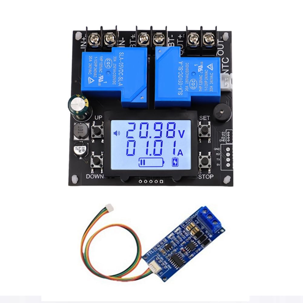
Figure 4: Visual guide to the operating modes: Charging, Discharge, and UPS Uninterruptible Power Supply. The display icons and current readings indicate the active mode.
6.1 Charging Mode
- When entering the charging state, the charging relay closes.
- The charging icon flashes, indicating the battery capacity.
- The icon will dynamically display charging progress.
- Charging mode button instructions: Press the STOP button briefly to stop charging. Long press the STOP button to force switch to discharge mode.
6.2 Discharge Mode
- When entering the discharge state, the discharge relay closes.
- The discharge icon flashes, and the battery capacity chart appears.
- The indicator will dynamically display the discharge progress.
- Discharge mode key instructions: Press the STOP button briefly to stop discharging. Long press the STOP button to force switch to charging mode.
6.3 UPS Uninterruptible Power Supply Mode
In UPS mode, the charging relay and discharge relay are always in the same state. When the charger is connected, it charges the battery and supplies power to the load. When the battery is fully charged, the charge current cuts off, but the electrical relay does not disconnect. When the charger is powered off, or the pool power has been exhausted, the module automatically switches to supply power to the load from the battery.
- Note: This mode must ensure the output of the charger is greater than the charging power plus the load power.
- The simultaneous flashing of the charging and discharging icons represents the UPS mode.
- Current description in UPS mode: When the charger charges the battery and supplies power to the load, the current displayed is the charging current for the battery. When the charger is disconnected (or the charger malfunctions), the charging icon will enter a rapid flashing mode to prompt charging. When an electrical appliance malfunctions, the battery will automatically supply power to the load, and the current displayed is the battery's discharge current.
How to turn on or off the UPS mode:
Long press the SET button to enter the Settings. If the FUC parameter is set to UPS, the UPS mode will be activated. Set it to other values to turn off the UPS mode.
UPS uninterruptible power supply mode button instructions: Press the STOP button briefly for emergency stop.
7. Maintenance
- Keep the module clean and free from dust and debris.
- Ensure proper ventilation around the module to prevent overheating.
- Regularly check all wiring connections for tightness and signs of corrosion.
- Avoid exposing the module to extreme temperatures or humidity.
8. Troubleshooting
If you encounter issues with your XY-BT13L module, consider the following common problems and solutions:
- Module not powering on: Check input voltage and polarity. Ensure connections are secure.
- Battery not charging/discharging: Verify battery connections and polarity. Check if the module is in the correct operating mode. Ensure the charger/load is functioning correctly.
- Inaccurate readings: Ensure all connections are tight. If issues persist, the module may require recalibration (refer to advanced settings if available, or contact support).
- Overheating: Ensure adequate ventilation. Reduce load if consistently overheating.
- Unexpected mode changes: Review button press sequences and settings, especially for UPS mode activation.
For persistent issues not covered here, please contact Yaregelun customer support.
9. Warranty and Support
The Yaregelun XY-BT13L module is manufactured with quality and reliability in mind. For specific warranty details, please refer to the product packaging or contact your point of purchase. For technical support or inquiries, please reach out to Yaregelun customer service.