1. Introduction
This manual provides essential information for the installation, configuration, operation, and maintenance of your Zyyini X99H Motherboard Kit. Please read these instructions carefully before proceeding with installation to ensure proper setup and optimal performance. Retain this manual for future reference.
2. Product Overview
The Zyyini X99H Motherboard is designed for high-performance computing, offering robust compatibility and expansion options. It supports a range of CPUs and memory configurations, making it suitable for various computing needs.
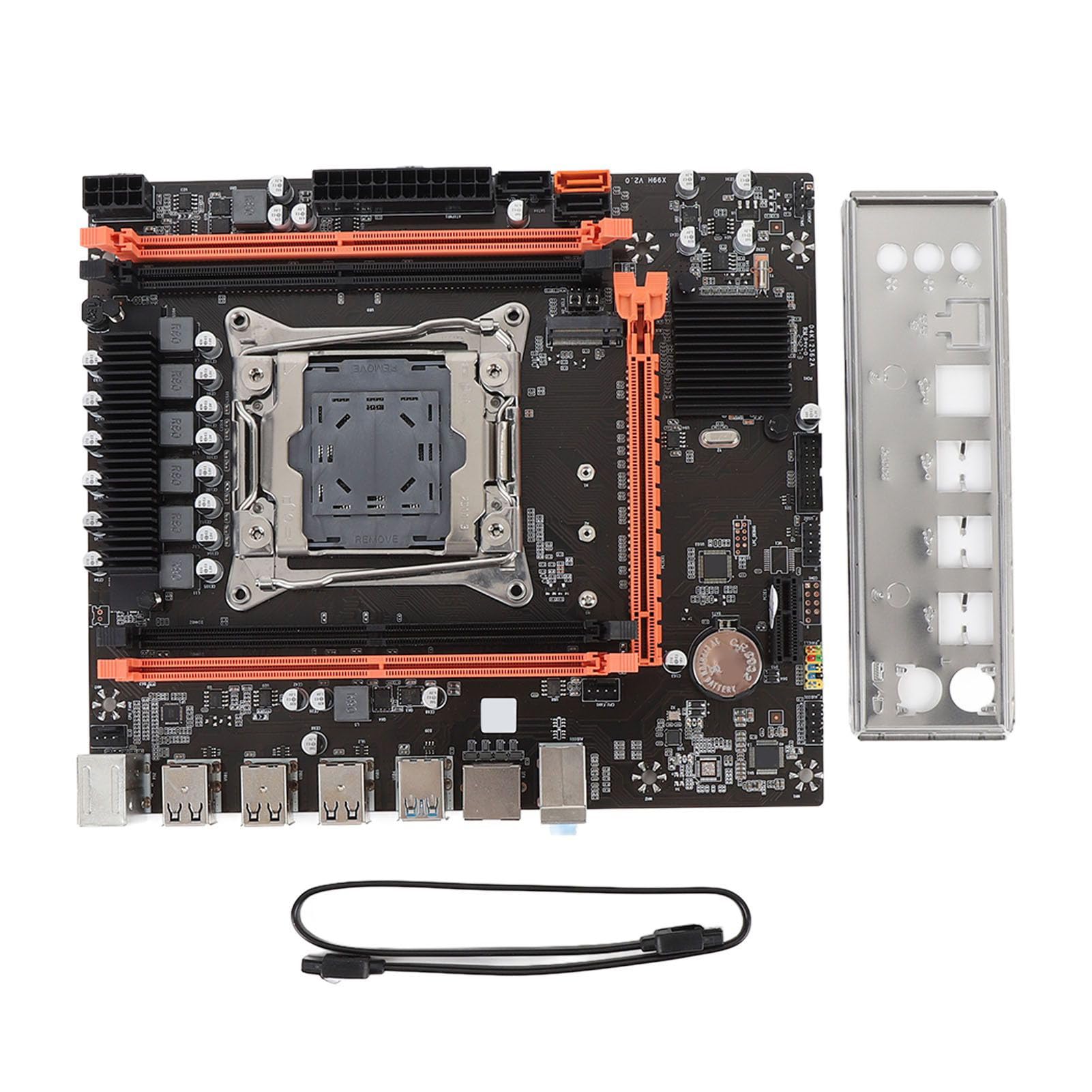
Figure 2.1: Overview of the Zyyini X99H Motherboard Kit.
Key Features:
- Strong Compatibility: Features an LGA 2011-3 CPU socket, supporting Intel E5 V3/V4 and i7 58xx/68xx series processors. Includes one 8-pin and one 24-pin power socket for stable power delivery.
- Impressive Memory Support: Equipped with four DDR4 DIMM slots, supporting up to 128GB of DDR4 memory at speeds of 2666, 2400, or 2133MHz.
- Serial ATA Ports: Includes Serial ATA ports for compact and easy storage device installation, ensuring high compatibility.
- Stable Performance: Utilizes all solid capacitors for enhanced stability and extended operational lifespan, contributing to reliable motherboard performance.
- Easy Expansion: Provides HD multimedia (HDMI) and VGA interfaces for display output, along with an M.2 slot that supports both NGFF and NVME protocols for high-speed storage expansion. It also features a PCI Express 16X slot for graphics cards.
3. Specifications
Below are the detailed technical specifications for the Zyyini X99H Motherboard Kit:

Figure 3.1: Top-down view of the Zyyini X99H Motherboard, highlighting component layout.
| Feature | Specification |
|---|---|
| Motherboard Structure | M-ATX |
| Chipset | X99H |
| CPU Socket | LGA 2011-3 |
| Supported CPU Types | Intel E5 V3/V4, i7 58xx/68xx series |
| Memory Type | DDR4 2666/2400/2133MHz |
| Memory Slots | 4 x DDR4 DIMM |
| Maximum Memory Capacity | 128GB |
| Graphics Card Standard Support | PCI Express 16X |
| Expansion Slots | 1 x PCIE x16, 1 x PCIE x1, 1 x NVME M.2 Interface (Serial ATA, PCIE with Jumper Switch) |
| USB Interfaces | 6 x USB 2.0, 2 x USB 3.0 (rear I/O), USB3.0 Pins (1 Set), USB2.0 Pins (1 Set) |
| Serial ATA Ports | 2 x Serial ATA 2.0, 1 x Serial ATA 3.0 |
| Video Outputs | HDMI, VGA |
| Network Interface | 1 x RJ45 |
| PS/2 Interface | 1 x PS/2 Keyboard/Mouse Universal Interface |
| Built-in Battery | CR2032x1 240mah |
4. Setup and Installation
Proper installation is crucial for the stability and performance of your system. Follow these steps carefully.
4.1. Preparation
- Ensure your workspace is clean and well-lit.
- Gather necessary tools: Phillips head screwdriver, anti-static wrist strap (recommended).
- Discharge static electricity by touching a grounded metal object before handling components.
4.2. CPU Installation
Carefully install your LGA 2011-3 processor into the CPU socket.
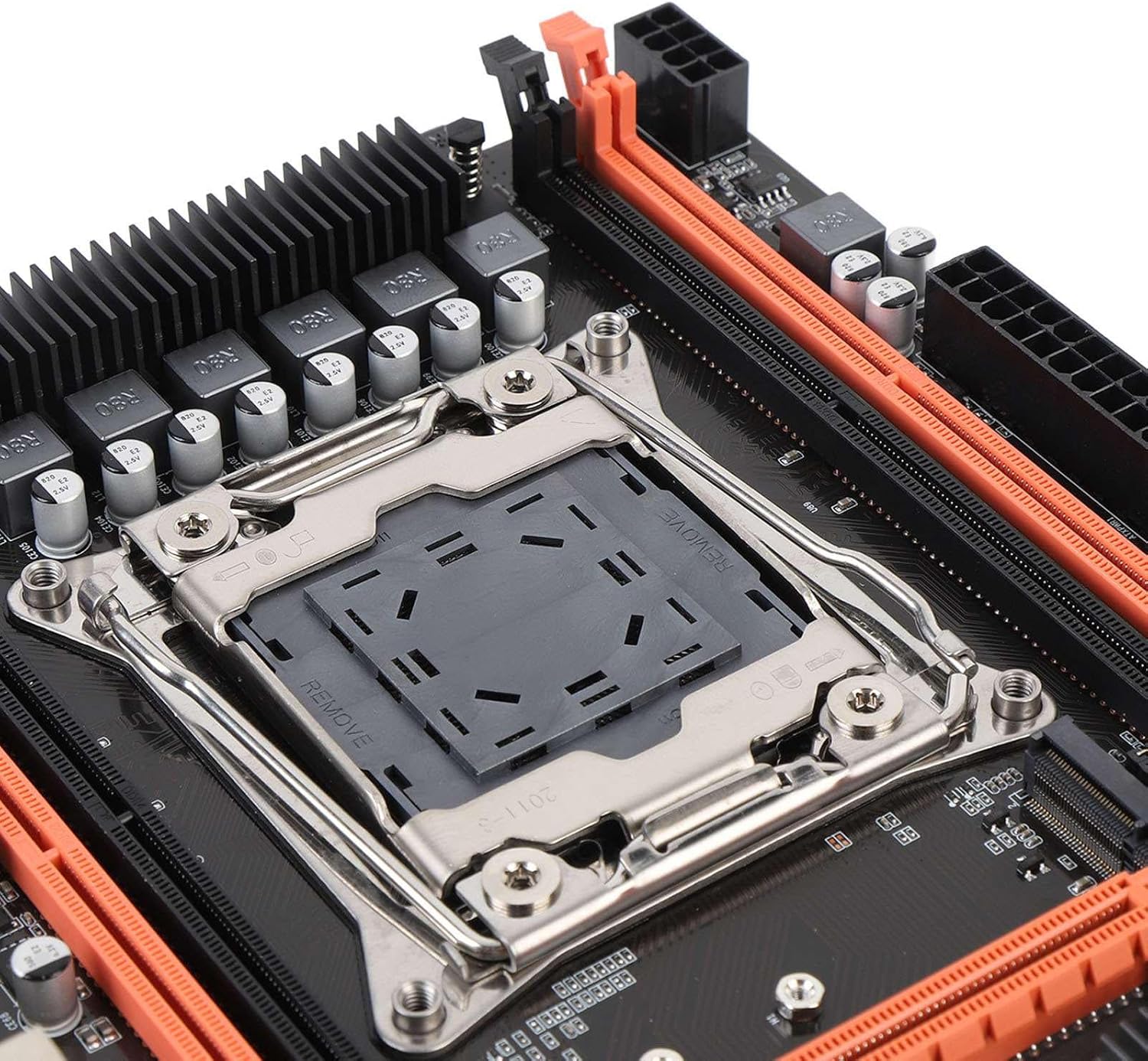
Figure 4.1: Close-up view of the LGA 2011-3 CPU socket.
- Open the CPU socket retention mechanism.
- Align the CPU with the socket, ensuring the gold triangle on the CPU matches the indicator on the socket.
- Gently place the CPU into the socket without forcing it.
- Close the retention mechanism to secure the CPU.
- Install the CPU cooler according to its manufacturer's instructions.
4.3. RAM Installation
Install DDR4 memory modules into the DIMM slots.
- Open the clips at both ends of the DIMM slots.
- Align the memory module with the slot, ensuring the notch on the module matches the key in the slot.
- Press down firmly on both ends of the memory module until the clips snap into place.
4.4. Motherboard Mounting
Mount the motherboard into your PC case.
- Install the I/O shield into the case's rear opening.
- Align the motherboard with the standoffs in your PC case.
- Secure the motherboard with screws.
4.5. Connecting Power
Connect the power supply unit (PSU) cables to the motherboard.
- Connect the 24-pin ATX power cable to the main power connector.
- Connect the 8-pin CPU power cable to the CPU power connector.
4.6. Connecting Storage Devices
Connect your SATA and NVME M.2 storage devices.

Figure 4.2: Close-up view of the M.2 slot and SATA ports.
- For SATA drives, connect one end of the SATA data cable to the motherboard's SATA port and the other to the drive. Connect the SATA power cable from the PSU to the drive.
- For NVME M.2 SSDs, insert the M.2 module into the M.2 slot and secure it with the provided screw.
4.7. Connecting Peripherals and Front Panel
Connect USB devices, front panel connectors, and other I/O.

Figure 4.3: Close-up view of the rear I/O ports.
- Connect your mouse and keyboard to the PS/2 or USB ports.
- Connect front panel USB, audio, power switch, reset switch, and LED indicators to the corresponding headers on the motherboard. Refer to your PC case manual for specific pin assignments.
- Connect network cables to the RJ45 port.
4.8. Graphics Card Installation
Install your PCI Express graphics card.
- Open the retention clip on the PCIe x16 slot.
- Align the graphics card with the slot and press down firmly until it clicks into place.
- Secure the graphics card to the case with a screw.
- Connect any required PCIe power cables from the PSU to the graphics card.
5. Operating Instructions
Once all components are installed, you can proceed with powering on your system.
5.1. First Boot
- Ensure all power cables are securely connected and the power supply is switched on.
- Press the power button on your PC case.
- The system should power on, and you should see a display on your monitor.
5.2. BIOS/UEFI Access
The BIOS (Basic Input/Output System) or UEFI (Unified Extensible Firmware Interface) allows you to configure fundamental system settings.
- During system startup, repeatedly press the designated key (commonly DEL, F2, F10, or F12) to enter the BIOS/UEFI setup utility.
- Within the BIOS/UEFI, you can adjust boot order, system time, fan speeds, and other hardware-related settings.
5.3. Driver Installation
After installing your operating system, install the necessary drivers for your motherboard and other components.
- Obtain the latest drivers from the Zyyini website or the component manufacturers' websites (e.g., chipset, audio, LAN, graphics card).
- Install drivers in the recommended order (typically chipset first, then graphics, audio, LAN, etc.).
5.4. Operating System Installation
Install your preferred operating system (e.g., Windows, Linux) from a bootable USB drive or DVD.
- Configure the boot order in BIOS/UEFI to prioritize your installation media.
- Follow the on-screen instructions of your operating system installer.
6. Maintenance
Regular maintenance helps ensure the longevity and stable operation of your motherboard and system.
- Keep it Clean: Periodically clean dust from inside your PC case, especially around fans and heatsinks, using compressed air. Ensure the system is powered off and unplugged before cleaning.
- Check Connections: Occasionally verify that all cables (power, data, peripheral) are securely connected to the motherboard and other components.
- BIOS/UEFI Updates: Check the Zyyini support website for BIOS/UEFI updates. Updates can improve compatibility, stability, and performance. Follow update instructions carefully to avoid system damage.
- Software Updates: Keep your operating system and drivers updated to ensure optimal performance and security.
7. Troubleshooting
This section provides solutions to common issues you might encounter.
7.1. No Power / System Does Not Turn On
- Check Power Connections: Ensure the 24-pin ATX and 8-pin CPU power cables are firmly connected to the motherboard and the power supply.
- Power Supply Switch: Verify that the power switch on the PSU is in the 'ON' position.
- Front Panel Connectors: Double-check the power switch connector on the motherboard's front panel header.
- Wall Outlet: Test the wall outlet with another device to ensure it has power.
7.2. No Display on Monitor
- Monitor Connection: Ensure the display cable (HDMI/VGA) is securely connected to both the graphics card/motherboard and the monitor.
- Graphics Card: If using a dedicated graphics card, ensure it is properly seated in the PCIe slot and any required power cables are connected.
- RAM: Reseat the RAM modules. Try booting with only one RAM stick if you have multiple.
- CPU: Ensure the CPU is correctly installed and the CPU cooler is making proper contact.
7.3. System Instability / Random Crashes
- Overheating: Check CPU and GPU temperatures. Ensure all fans are working correctly and heatsinks are free of dust.
- RAM Issues: Run a memory diagnostic tool (e.g., Windows Memory Diagnostic) to check for faulty RAM.
- Driver Issues: Ensure all drivers are up-to-date and correctly installed.
- Power Supply: An insufficient or failing power supply can cause instability.
7.4. Component Not Detected (e.g., Storage, USB Device)
- Check Connections: Verify that the component's power and data cables are securely connected.
- BIOS/UEFI Settings: Check if the component is enabled in the BIOS/UEFI settings. For M.2 drives, ensure the correct protocol (NVME/SATA) is selected if applicable via jumper switch.
- Drivers: Install the latest drivers for the component.
- Device Manager: In your operating system, check Device Manager (Windows) or equivalent to see if the device is listed, even with an error.
8. Support and Warranty
For technical support or warranty inquiries, please contact Zyyini customer service through the retailer where you purchased the product or visit the official Zyyini support website. Please have your product model (X99H) and purchase information ready when contacting support.
Specific warranty terms and conditions may vary by region and retailer. Please refer to your purchase documentation for detailed warranty information.