1. Introduction
The AnyTone AT-5289 II is a high-power 10 Meter Mobile Ham Radio designed for robust communication. This manual provides essential information for the proper setup, operation, and maintenance of your device. Please read it thoroughly to ensure safe and effective use.
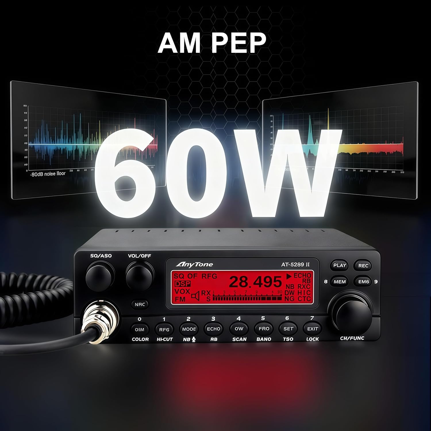
Image 1: The AnyTone AT-5289 II Mobile Ham Radio main unit, featuring its front panel controls and display.
2. Key Features
- True High Power Performance: Delivers 50W on FM and 20W carrier power on AM, reaching up to 60W PEP (Peak Envelope Power) for strong RF penetration and long-distance communication.
- Dual NRC Noise Reduction: Features advanced RX and TX NRC digital noise reduction with 5 adjustable levels to suppress background interference. Combined with ASQ (Automatic Squelch) and NB/ANL filtering for clear audio.
- VFO Mode & Versatile Tuning: Supports full VFO mode for precise frequency tuning across 28.000–29.700MHz with selectable steps (1kHz, 10kHz, 100kHz, or 1MHz). Note: This is an AM/FM ONLY transceiver and does NOT support SSB (Single Side Band) mode.
- Multi-Color LCD & Intelligent Monitoring: 7-color selectable backlight with dimming for easy reading. Displays real-time data including frequency, channel, SWR protection status, and voltage levels.
- Built-in Safety & PC Programmable: Equipped with a standard SO-239 antenna port, external speaker jack, hand microphone, power cable, and mounting bracket. Voltage and SWR protection prevent equipment damage.

Image 2: The AnyTone AT-5289 II showcasing its NRC Noise Reduction capabilities, illustrating how it filters out background interference for clearer communication.
3. Included Components
The AnyTone AT-5289 II package includes the following items:
- 10 Meter Amateur Radio Unit
- Hand Microphone
- Installation Bracket
- Power Cable
- Owner's Manual
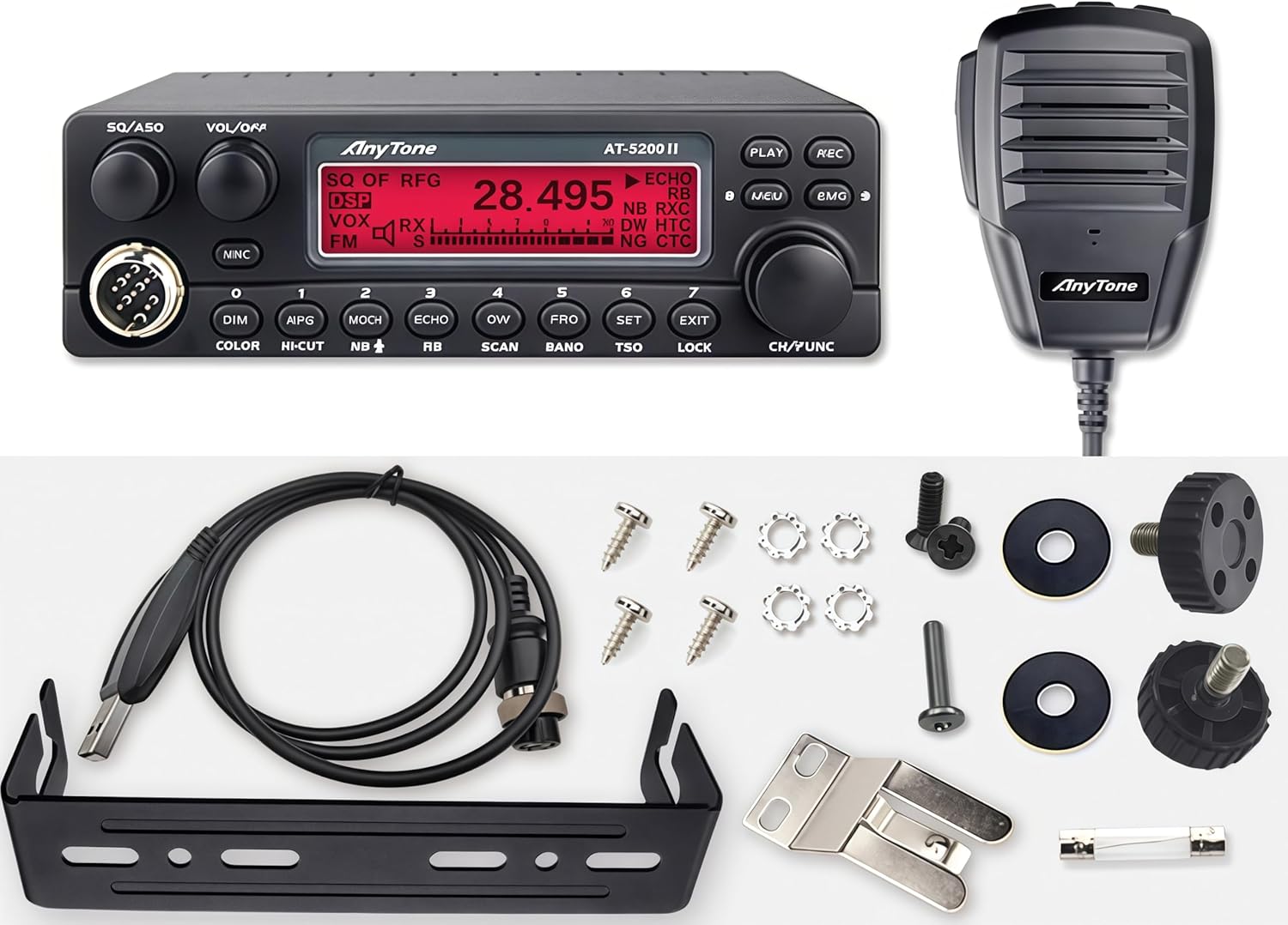
Image 3: A visual representation of all items included in the AnyTone AT-5289 II package, including the radio unit, microphone, mounting hardware, and cables.
4. Setup and Installation
4.1 Mounting the Radio
Use the provided mounting bracket to secure the radio in a suitable location within your vehicle (trucks, SUVs, off-road rigs, overlanding setups). Ensure the location allows for proper ventilation and easy access to controls.
4.2 Power Connection
Connect the supplied power cable to a 13.2V DC power source. Ensure correct polarity (red to positive, black to negative) and that the power source can supply a maximum of 15A. The radio features voltage protection to prevent damage from fluctuations.
4.3 Antenna Connection
Connect a compatible 10-meter antenna to the standard SO-239 antenna port on the rear of the radio. Ensure the antenna is properly tuned for the 10-meter band to prevent high SWR, which can damage the radio. The radio includes SWR protection.
4.4 Microphone and External Speaker
Plug the hand microphone into the 6-pin microphone port on the front panel. An external speaker can be connected to the 3.5mm jack on the rear for enhanced audio clarity.
5. Basic Operation
5.1 Power On/Off and Volume
Turn the VOL/OFF knob clockwise to power on the radio and adjust the audio volume. Turn counter-clockwise until it clicks to power off.
5.2 Squelch Adjustment
The SQ/ASQ knob controls the squelch level. Rotate it clockwise to increase the squelch threshold, silencing background noise. Rotate counter-clockwise to decrease it, allowing weaker signals to be heard. The ASQ (Automatic Squelch) function can be activated for automatic noise suppression.
5.3 Frequency Tuning
Use the main rotary encoder on the right side of the front panel to tune the frequency. Short presses on the FRQ button allow selection of tuning steps (1kHz, 10kHz, 100kHz, 1MHz).
5.4 Mode Selection
Press the MODE button to cycle between AM and FM modulation modes. Note that this radio does not support SSB.

Image 4: Close-up of the AnyTone AT-5289 II's multi-color LCD display, showing various color options and real-time operational data.
6. Advanced Features
6.1 NRC Noise Reduction
Activate the NRC button to engage the digital noise reduction system. Adjust the NRC level through the menu settings to optimize for your operating environment.
6.2 Memory Channels
The radio supports VFO and memory channels. Use the MEM button to access and store frequently used frequencies. Refer to the owner's manual for detailed instructions on programming memory channels.
6.3 Display Customization
Press the COLOR button to cycle through the 7 available backlight colors for the LCD display. The DIM button allows adjustment of the display brightness.
6.4 PC Programming
The AnyTone AT-5289 II is PC programmable. Connect the radio to your computer using a compatible programming cable (not always included, check package contents) and use the dedicated software to customize settings, memory channels, and other parameters. Software and guides are available in the "Safety Information" section of the product page or by contacting support.
Video 1: An overview of the AnyTone AT-5289 II 10 Meter Mobile Ham Radio, demonstrating its features, controls, and operational modes. This video provides a visual guide to the radio's capabilities and user interface.
7. Specifications
| Feature | Specification |
|---|---|
| Product Dimensions | 6.65 x 6.26 x 1.89 inches (169 x 159 x 48 mm) |
| Item Weight | 2.25 pounds (1.02 kg) |
| Frequency Range | 28.000–29.700MHz |
| Modulation Modes | AM, FM (No SSB) |
| Output Power (FM) | 50W |
| Output Power (AM) | 20W Carrier (60W PEP) |
| Power Source | Corded Electric (DC 13.2V, Max 15A) |
| Antenna Port | SO-239 |
| Special Features | Automatic Squelch, Digital Display, Weather Alert, NRC Noise Reduction |
8. Troubleshooting
If you encounter issues with your AnyTone AT-5289 II, please refer to the troubleshooting section in the full owner's manual. Common issues and their solutions are detailed there. Ensure all connections are secure and power supply is stable.
9. Warranty and Support
User manuals, PC programming software, and detailed operational guides are available for download in the "Safety Information" section of this product page. If you cannot locate these files or need further technical assistance, please contact our support team directly. We are committed to providing immediate response and full technical documentation to ensure you get the most out of your radio.