Introduction
The eletechsup ESC3E05 is an ESP32 C3 Super Mini expansion board designed for various Internet of Things (IoT) and automation applications. This compact board features 4 relay outputs, an RS485 bus interface, and exposes additional I/O pins for versatile use. It requires an ESP32 C3 Super Mini board (not included) to function.
This manual provides essential information for the proper setup, operation, and maintenance of your ESP32 C3 Relay Module.
Product Features
- Operating Voltage: DC 7-25V
- Operating Current:
- Standby: 14mA
- 1 Relay Open: 75mA
- 2 Relays Open: 106mA
- 3 Relays Open: 131mA
- 4 Relays Open: 163mA
- On-board Resources:
- 1x RS485 Interface
- 4x Relay Outputs (10A)
- 6x 3.3V Common IO Ports
- 4x 0-3V Analog Acquisition Ports (multiplexed D0, D1, D3, D4)
- 1x ESP32 C3 Super Mini Socket
- RS485 Interface: High-speed, Baud Rate 0.05K-1000KBPS
- Terminal Spacing: 3.96mm
- Terminal Blocks: Wire Range 26-16AWG, Strip Length 3.96mm, Metric M2/M2.5 Slotted Screws
- Dimensions (Only Board): 75 x 50 x 12mm
- Weight (Only Board): 45g
Specifications
| Attribute | Value |
|---|---|
| Brand | eletechsup |
| Model | Only Board (DNDINS3) |
| ASIN | B0G1BD7J5R |
| GTIN/UPC | 740991699868 |
| Manufacturer | eletechsup |
| Included Components | Only Board (ESP32 C3 Super Mini not included) |
Note: The "Only Board" variant refers to the PCB without the optional DIN rail enclosure. If you purchased the "With Shell" variant, it includes the DIN rail box.
Setup
1. Inserting the ESP32 C3 Super Mini Board
The ESC3E05 expansion board requires a 16-pin ESP32 C3 Super Mini board to operate. Ensure the ESP32 C3 Super Mini board is correctly oriented and gently insert it into the designated socket on the ESC3E05 board.

Image: Illustration of the ESP32 C3 Super Mini board being inserted into the ESC3E05 expansion board. The image also shows the "Only Board" variant and the "With DIN Box" variant for comparison.
2. Power Connection
Connect a DC power supply within the 7-25V range to the "VIN" and "GND" terminals of the power input port. Observe polarity to prevent damage to the module.
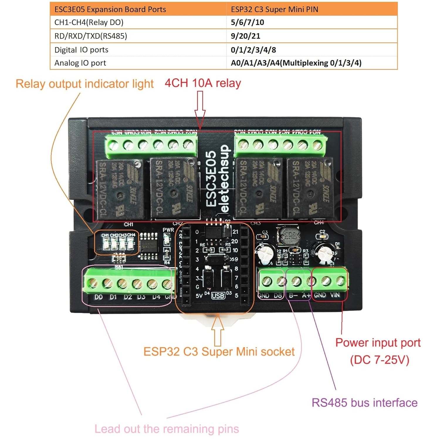
Image: Detailed component layout of the ESC3E05 board, highlighting the power input port (DC 7-25V), 4-channel 10A relays, RS485 bus interface, and the ESP32 C3 Super Mini socket.
3. Relay Connections
The module provides four relay outputs (CH1-CH4). Each relay has Normally Open (NO), Normally Closed (NC), and Common (COM) terminals. Connect your load according to your application requirements. The relay output indicator lights will illuminate when a relay is activated.

Image: Connection diagram for the ESC3E05 board, showing how to connect loads to the relays, the DC 7-25V power input, RS485 connections, and the breakout of remaining IO ports (D0, D1, D3, D4 for digital I/O and 0-3V analog acquisition).
4. RS485 Interface
The RS485 interface (A+, B-) allows for serial communication. Connect to other RS485 devices for master-slave configurations or data exchange. Refer to the ESP32 C3 documentation for specific RS485 library usage.
5. IO Port Connections
The remaining 3.3V common IO ports and 0-3V analog acquisition ports (D0, D1, D3, D4) are broken out for additional sensor inputs or control signals. These can be used for various functions such as NPN/PNP digital inputs or voltage collection.
Operating Instructions
The ESC3E05 module functions under the control of the inserted ESP32 C3 Super Mini board. Programming is done via the ESP32 C3 board using development environments like Arduino IDE.
1. Programming the ESP32 C3
Develop your application code for the ESP32 C3 Super Mini board. This code will define the logic for controlling the relays, reading analog inputs, and managing RS485 communication. Basic Arduino code examples for hardware testing may be available from the manufacturer, but custom functionality requires user development.
- Relay Control: Map the relay control pins (CH1-CH4) to specific GPIOs on the ESP32 C3.
- Analog Acquisition: Utilize the D0, D1, D3, D4 pins for 0-3V analog voltage collection.
- RS485 Communication: Implement RS485 protocols for master-slave communication or data transfer.
- WIFI/IOT Functions: Leverage the ESP32 C3's built-in Wi-Fi capabilities for remote control and IoT integration.
Refer to the ESP32 C3 Super Mini documentation and pinout for accurate GPIO mapping.
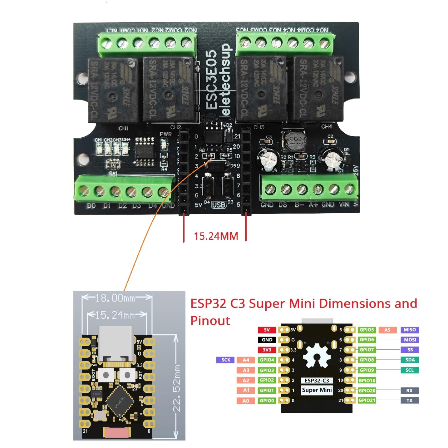
Image: Dimensions and pinout diagram for the ESP32 C3 Super Mini board, essential for programming and connecting to the ESC3E05 expansion board.
Maintenance
- Cleaning: Keep the board free from dust and debris. Use a soft, dry brush or compressed air for cleaning. Avoid liquids.
- Environmental Conditions: Operate the module within recommended temperature and humidity ranges. Avoid extreme conditions.
- Connections: Periodically check all terminal connections to ensure they are secure. Loose connections can lead to intermittent operation or damage.
- Power Supply: Ensure the power supply voltage remains within the specified DC 7-25V range.
Troubleshooting
- Module Not Powering On:
- Verify the DC power supply is connected correctly (7-25V, correct polarity).
- Ensure the ESP32 C3 Super Mini board is properly seated in its socket.
- Relays Not Activating:
- Check your ESP32 C3 code to ensure the correct GPIOs are being toggled for relay control.
- Confirm the power supply is sufficient for both the module and the connected loads.
- Inspect relay connections for proper wiring (NO, NC, COM).
- RS485 Communication Issues:
- Verify A+ and B- connections are correct and not swapped.
- Check baud rate settings in your code match the connected RS485 device.
- Ensure proper termination resistors are used in the RS485 network if applicable.
- Analog Input Readings Incorrect:
- Ensure input voltage is within the 0-3V range for the analog acquisition ports.
- Check wiring to the D0, D1, D3, D4 pins.
- Review your ESP32 C3 code for correct ADC configuration and reading.
Warranty and Support
This product comes with a limited warranty. For specific warranty terms and conditions, please refer to the purchase documentation or contact eletechsup customer support. Technical support for custom code development is not provided; users are expected to develop their own code based on ESP32 C3 documentation.
For further assistance, please visit the eletechsup Store on Amazon.