1. Introduction
This manual provides detailed instructions for the installation, operation, and maintenance of your ciciglow H510 ITX Motherboard. Designed for 10th and 11th Generation Intel LGA 1200 processors, this mini-ITX board offers robust performance with dual-channel DDR4 memory support, M.2 NVMe slot, and PCIe 3.0 x16 expansion capabilities. Please read this manual thoroughly before proceeding with installation.
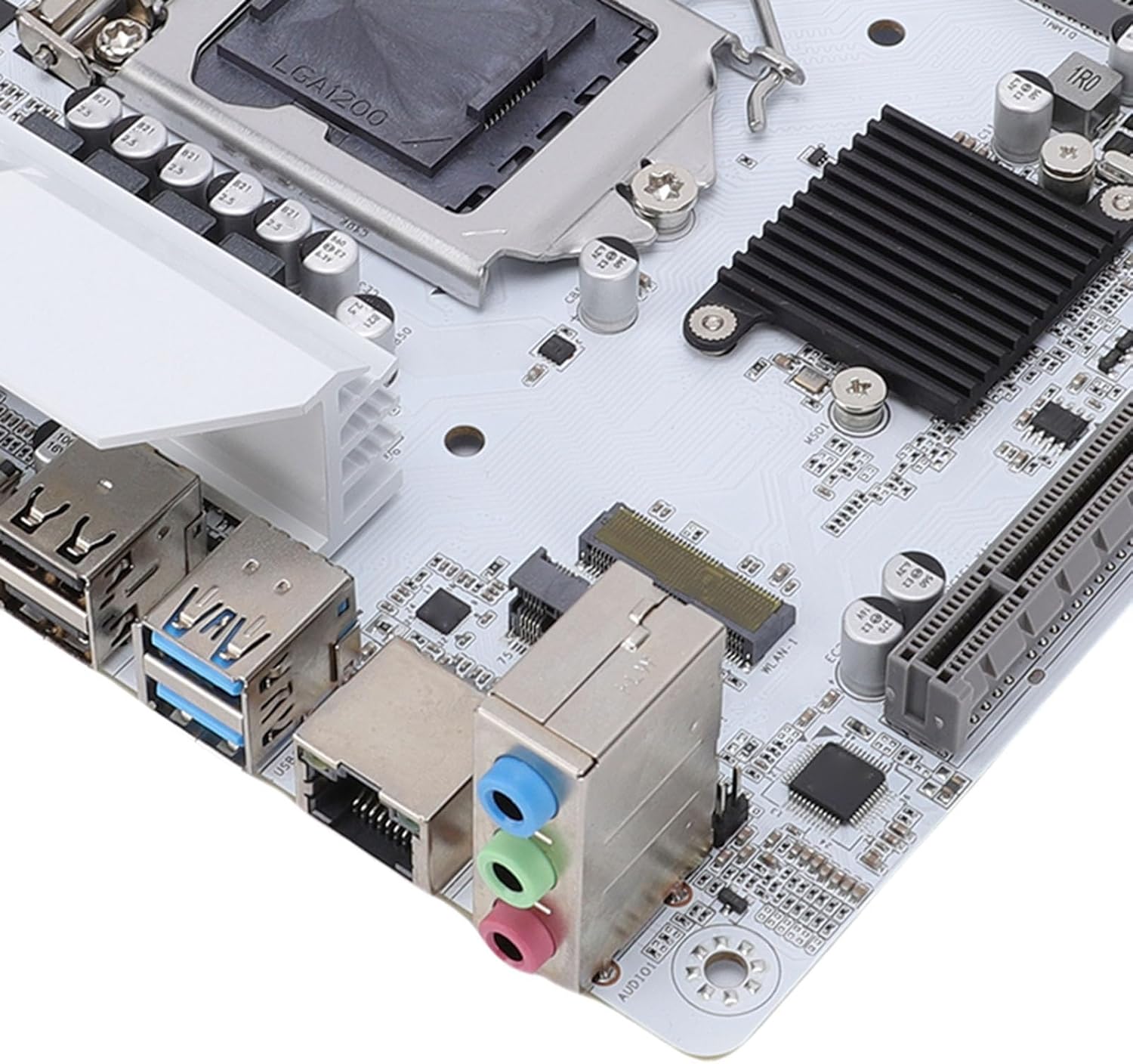
Figure 1.1: Overview of the ciciglow H510 ITX Motherboard. This image displays the compact layout of the motherboard, highlighting the CPU socket, RAM slots, and various connectors.
2. Setup and Installation
Follow these steps to properly install your ciciglow H510 ITX Motherboard into your computer system.
2.1. Package Contents
Verify that your package contains the following items:
- 1 x ciciglow H510 ITX Computer Motherboard
- 1 x I/O Shield Bracket
2.2. CPU Installation
- Carefully open the CPU socket retention lever.
- Align the CPU (LGA 1200) with the socket, ensuring the gold triangle on the CPU matches the indicator on the socket.
- Gently place the CPU into the socket without forcing it.
- Close the retention lever to secure the CPU.
- Apply thermal paste and install the CPU cooler (not included).
2.3. Memory (RAM) Installation
The motherboard supports dual-channel DDR4 memory up to 64GB (2x32GB) at frequencies up to 3000MHz.
- Locate the two DDR4 DIMM slots.
- Open the clips at both ends of the DIMM slot.
- Align the notch on the DDR4 memory module with the key in the DIMM slot.
- Insert the memory module firmly until the clips snap into place.
2.4. Storage Device Installation
The motherboard includes an M.2 slot (NVMe Protocol: Gen3X4) and four Serial ATA 3.0 interfaces.
2.4.1. M.2 NVMe SSD Installation
- Locate the M.2 slot on the motherboard.
- Remove the M.2 standoff screw.
- Insert the M.2 NVMe SSD into the slot at an angle.
- Gently push down the SSD and secure it with the standoff screw.
2.4.2. SATA Drive Installation
- Connect one end of a SATA data cable to a SATA 3.0 port on the motherboard.
- Connect the other end of the SATA data cable to your SATA hard drive or SSD.
- Connect a SATA power cable from your power supply to the SATA drive.
2.5. Expansion Card Installation
The motherboard features one PCIe x16 slot (PCIe 3.0 x16) for graphics cards and one M.2 WiFi slot (PCIe protocol only) for wireless connectivity.

Figure 2.1: Extensive Expansion Capabilities. This image highlights the PCIe x16 slot and the M.2 WiFi expansion slot, allowing for additional components like discrete graphics cards or wireless modules.
- Locate the desired expansion slot.
- Remove the corresponding slot cover from your PC case.
- Align the expansion card with the slot and press firmly until it is seated correctly.
- Secure the card with a screw to the PC case.
2.6. Power Connections
Connect the 24-pin ATX power connector and the 8-pin ATX 12V power connector from your power supply to the motherboard.
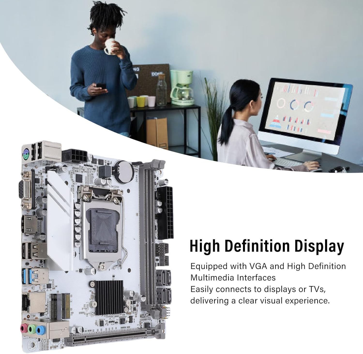
Figure 2.2: Stable Power Delivery. This image illustrates the 24-pin and 8-pin power connectors, crucial for providing stable power to the motherboard and its components.
2.7. Connecting Peripherals
Connect your display, USB devices, network cable, and audio devices to the appropriate ports on the motherboard's I/O panel.
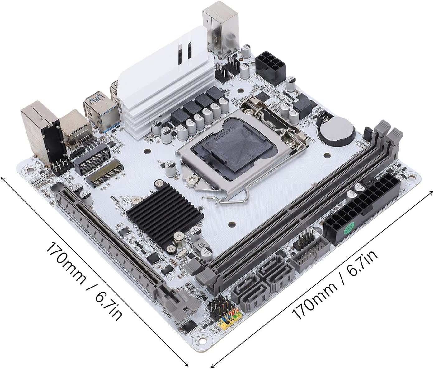
Figure 2.3: High Definition Display Output. This image shows the VGA and HD Multimedia Interface 2.0 ports, enabling connection to various display devices for high-definition visuals.
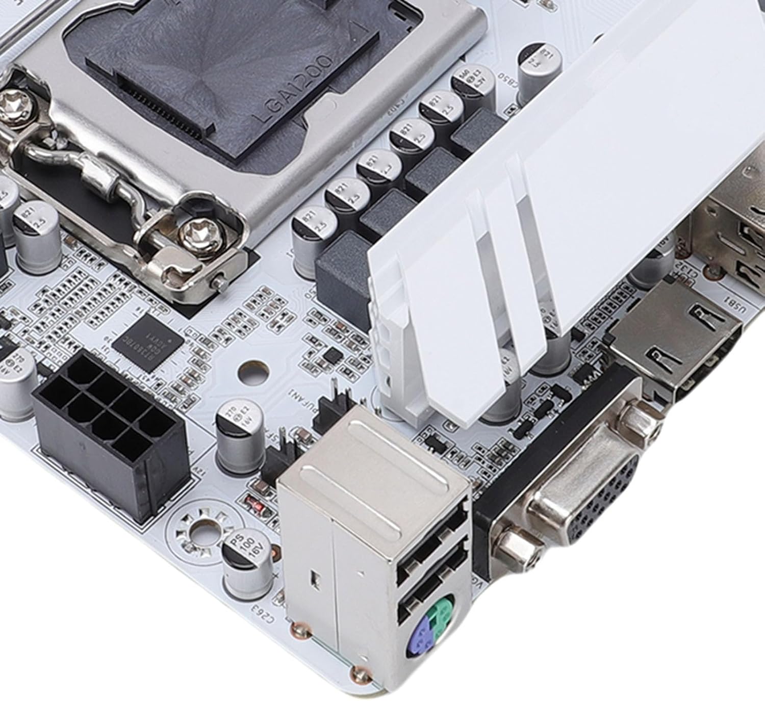
Figure 2.4: Rear I/O Ports. A detailed view of the motherboard's rear input/output panel, featuring USB 3.0, USB 2.0, audio jacks, and network port.
Figure 2.5: Power and Display Connections. This image provides a closer look at the 24-pin power connector, VGA port, and HD Multimedia Interface on the motherboard.
3. Operating Instructions
Once all components are installed and connected, you can power on your system.
3.1. First Boot and BIOS Setup
- Power on your computer.
- Press the designated key (usually DEL or F2) repeatedly during startup to enter the BIOS/UEFI setup utility.
- Configure boot order, system time, and other necessary settings.
- Save changes and exit the BIOS.
3.2. Operating System Installation
Install your preferred operating system (e.g., Windows, Linux) from a bootable USB drive or DVD.
3.3. Driver Installation
After installing the operating system, install the necessary drivers for the motherboard components (chipset, network, audio, graphics) from the manufacturer's website or the included driver disk (if applicable) to ensure optimal performance.
4. Maintenance
Regular maintenance helps ensure the longevity and stable operation of your motherboard.
- Cleaning: Periodically clean dust from the motherboard and components using compressed air. Ensure the system is powered off and unplugged before cleaning.
- BIOS/UEFI Updates: Check the ciciglow official website for the latest BIOS/UEFI updates. Follow the provided instructions carefully when updating to improve compatibility and performance.
- Driver Updates: Keep your drivers updated to ensure system stability and access to the latest features.
5. Troubleshooting
This section addresses common issues you might encounter.
5.1. No Display Output
- Ensure the monitor is connected to the correct display output on the motherboard or graphics card.
- Check that the graphics card (if installed) is properly seated and has power.
- Verify that RAM modules are correctly installed. Try reseating them or testing with one module at a time.
- Ensure the CPU power connector (8-pin) is securely connected.
5.2. System Fails to Boot
- Check all power connections (24-pin ATX, 8-pin CPU, SATA power).
- Ensure the CPU is correctly installed and the cooler is making proper contact.
- Verify that the RAM modules are properly seated.
- Disconnect all non-essential peripherals and try booting.
- Clear the CMOS (Complementary Metal-Oxide-Semiconductor) by removing the CR2032 battery for a few seconds or using the clear CMOS jumper (if available).
5.3. Operating System Not Detected
- Check SATA data and power cables for your storage drives.
- Ensure the M.2 NVMe SSD is properly installed.
- Verify the boot order in the BIOS/UEFI settings.
- Confirm that the operating system is correctly installed on the drive.
6. Specifications
Detailed technical specifications for the ciciglow H510 ITX Motherboard.

Figure 6.1: Motherboard Dimensions. This image shows the compact ITX form factor of the motherboard, measuring 170mm by 170mm (6.7 inches by 6.7 inches).
| Feature | Specification |
|---|---|
| Model | H510 ITX |
| Form Factor | Mini ITX (170x170mm / 6.7x6.7in) |
| CPU Support | 10th and 11th Generation Intel Core Processors (LGA 1200) |
| Memory | 2 x DDR4 DIMM slots, Dual Channel, Max 64GB (2x32GB) Supported Frequencies: 3000, 2933, 2800, 2666, 2400, 2133MHz |
| Storage | 1 x M.2 Slot (NVMe Protocol: Gen3X4) 4 x Serial ATA 3.0 Interfaces |
| Expansion Slots | 1 x PCIe x16 Slot (PCIe 3.0 x16) 1 x M.2 WiFi Slot (PCIe Protocol Only) |
| Video Output | 1 x HD Multimedia Interface 2.0 1 x VGA |
| Network | Realtek 8111H Gigabit Ethernet |
| Audio | REALTEK ALC897 High Definition Sound Chip 1 x LINE OUT, 1 x MIC IN, 1 x LINE IN, 1 x JAUDI01 Built-in Pin Header |
| USB Ports | Rear: 2 x USB 3.0, 4 x USB 2.0 Internal Pin Headers: 1 Group of FUSB20 (expandable to 2 USB 2.0 ports), 1 Group of FUSB30 (expandable to 2 USB 3.0 ports) |
| PS/2 Port | 1 |
| Power Input | 24-pin ATX Power Connector, 8-pin ATX 12V Power Connector |
| Battery | Built-in CR2032 240mAh Battery |
| Material | Premium PCB |
7. Warranty Information
Please refer to the warranty card included with your product or visit the official ciciglow website for detailed warranty terms and conditions. The warranty typically covers manufacturing defects for a specified period from the date of purchase.
8. Customer Support
If you encounter any issues or have questions regarding your ciciglow H510 ITX Motherboard, please contact ciciglow customer support through their official website or the contact information provided in your product packaging. For online resources, you may visit the ciciglow Store on Amazon.


