
1. Introduction
This manual provides essential information for the safe and efficient operation of your Generic 24V 5KW Hybrid Solar Inverter. This advanced inverter integrates solar power with grid electricity, offering reliable energy conversion and distribution for various applications. Please read this manual thoroughly before installation and use to ensure proper functionality and longevity of the product.
2. Product Features
The Generic 24V 5KW Hybrid Solar Inverter is designed with several key features to optimize your energy system:
- Power Output: 24V 5kW hybrid solar inverter with advanced power management system for efficient energy conversion and distribution.
- Digital Display: Large LCD screen interface showing real-time system status, power flow, and operational parameters for easy monitoring.
- Hybrid Functionality: Seamlessly integrates solar power and grid electricity, providing reliable backup power during outages.
- Smart Controls: Intuitive touch-button interface with four dedicated function keys for simplified system navigation and control.
- Ventilation Design: Perforated side panels ensure optimal thermal management and enhanced operational efficiency.
- High Power Input: MPPT input 27A high current + 9000W high power for efficient solar energy harvesting.
- Battery Management System (BMS): Built-in BMS chip for precise monitoring, protection, and optimization, making the battery system safer, more durable, and more efficient.
- Smart Online Management: Monitor production and energy consumption in real-time via a dedicated app for optimized energy independence.

Image: The Hybrid Solar Inverter 5KW 24V highlighting its key specifications including 9000W MPPT input power, 27A MPPT input current, 60-450VDC MPPT voltage, 160A Max AC Charging Current, and 160A Max Charge Current (PV+AC).

Image: Illustration emphasizing the inverter's 27A high current input and 9000W high power capability, ensuring efficient power tracking and maximum utilization of solar energy.

Image: A close-up of a circuit board highlighting the built-in Battery Management System (BMS) chip, which enhances the safety, durability, and efficiency of the inverter's battery system.

Image: The inverter mounted on a wall, with a smartphone displaying an application for smart online management, allowing users to monitor energy production and consumption in real-time.
3. Product Overview
Familiarize yourself with the components and controls of your hybrid solar inverter.

Image: Detailed diagrams showing the front and side panels of the inverter with numbered labels for each component and control button.
Front Panel Controls and Indicators:
- AC Indicator: Lights up when AC power is present.
- Invert Indicator: Lights up when the inverter is converting DC to AC.
- Charging Indicator: Lights up when batteries are being charged.
- Fault Indicator: Lights up to indicate a system error or fault.
- LCD Display: Shows real-time system status, parameters, and settings.
- ESC Button: Used to exit menus or cancel selections.
- Up Button: Used to navigate up in menus or increase values.
- Down Button: Used to navigate down in menus or decrease values.
- Enter Button: Used to confirm selections or enter menus.
Side Panel Connections:
- Power On/Off Switch: Main power control for the inverter.
- AC Input: Connection for grid AC power.
- AC Output 1: Primary AC output connection.
- AC Output 2: Secondary AC output connection.
- PV Input: Connections for solar panel arrays.
- Battery Input: Connections for battery bank.
- BMS Port: Communication port for Battery Management System.
- COM Port: General communication port (e.g., RS485/RS232/USB).
- AC Input Breaker: Circuit breaker for AC input protection.
- PE (Protective Earth): Grounding terminal.
4. Setup
Follow these steps for safe and correct installation of your hybrid solar inverter.
4.1 Unpacking and Inspection
- Carefully unpack the inverter and all accessories.
- Inspect for any shipping damage. Contact your supplier immediately if any damage is found.
- Verify that all items listed in the 'Box Contents' are present: Hybrid Solar Inverter, Display Panel, Mounting Hardware.
4.2 Mounting the Inverter
- Choose a suitable mounting location: indoors, well-ventilated, away from direct sunlight, heat sources, and flammable materials.
- Ensure the mounting surface can support the inverter's weight (9.5 kg).
- Use the provided mounting hardware to securely fasten the inverter to the wall. Allow sufficient clearance around the unit for ventilation.
4.3 Electrical Connections
WARNING: All electrical work must be performed by qualified personnel in accordance with local electrical codes and regulations.
- Battery Connection: Connect the battery bank to the Battery Input terminals. Ensure correct polarity (positive to positive, negative to negative).
- PV (Solar Panel) Connection: Connect the solar panel array to the PV Input terminals. Observe correct polarity and ensure the PV voltage is within the inverter's specified range (60-450VDC MPPT range, max 500V open circuit).
- AC Input (Grid) Connection: Connect the grid AC power supply to the AC Input terminal. Ensure proper wiring for L, N, and PE.
- AC Output (Load) Connection: Connect your loads to the AC Output 1 and AC Output 2 terminals.
- Grounding: Connect the PE (Protective Earth) terminal to a reliable ground point.
- Communication Connections: If using, connect the BMS and COM ports as required for external monitoring or battery communication.
5. Operating Instructions
5.1 Powering On the Inverter
- Ensure all electrical connections are secure and correct.
- Switch on the battery breaker (if applicable).
- Switch on the PV array breaker (if applicable).
- Switch on the AC input breaker.
- Press the Power On/Off switch on the inverter to turn it on. The LCD display will illuminate, and the inverter will begin its startup sequence.
5.2 LCD Display and Navigation
The LCD display provides real-time information and allows configuration of settings. Use the ESC, Up, Down, and Enter buttons to navigate through menus and adjust parameters.
- Monitoring: The default screen typically shows key operational data such as input voltage, output voltage, battery status, and power flow.
- Settings Menu: Press 'Enter' to access the main menu. Use 'Up'/'Down' to scroll through options and 'Enter' to select. Use 'ESC' to go back.
- Common Settings: These may include output voltage/frequency, charging current, battery type, and operating mode (e.g., grid-tie, off-grid, hybrid). Refer to the detailed settings section in the full manual for specific parameter adjustments.
5.3 Smart Online Management
Utilize the smart online management feature for remote monitoring and control:
- Connect the inverter to your local network via the WiFi dongle (if included/optional).
- Download the dedicated mobile application from your app store.
- Follow the app's instructions to register your inverter and begin monitoring its performance, energy production, and consumption in real-time.
6. Maintenance
Regular maintenance ensures optimal performance and extends the lifespan of your inverter.
- Cleaning: Periodically clean the inverter's exterior with a dry, soft cloth. Ensure ventilation openings are free from dust and debris. Do not use liquid cleaners.
- Connections: Annually check all electrical connections for tightness and signs of corrosion. Re-tighten if necessary.
- Ventilation: Ensure the area around the inverter remains clear to allow for proper airflow and cooling.
- Battery Inspection: If using lead-acid batteries, check electrolyte levels and terminal conditions as per battery manufacturer guidelines. For lithium batteries, monitor BMS data.
- Firmware Updates: Check with the manufacturer or supplier for any available firmware updates to improve performance or add features.
7. Troubleshooting
This section provides solutions for common issues. For complex problems, contact technical support.
| Problem | Possible Cause | Solution |
|---|---|---|
| Inverter not powering on | No battery power; Inverter switch off; Loose connections | Check battery voltage; Ensure inverter switch is ON; Verify all connections are secure. |
| No AC output | Overload; Short circuit; Inverter fault; AC output breaker tripped | Reduce load; Check for short circuits; Check fault codes on LCD; Reset AC output breaker. |
| Low PV input power | Shading on panels; Dirty panels; PV connection issue | Clear shading; Clean panels; Check PV wiring and connections. |
| Battery not charging | No PV input; No AC input; Battery fault; Charging settings incorrect | Check PV and AC inputs; Inspect battery health; Verify charging parameters in settings. |
| LCD display blank or error code | Power issue; Internal fault | Check power supply to inverter; Refer to the full manual for specific error code meanings. |
8. Specifications
Detailed technical specifications for the Generic 24V 5KW Hybrid Solar Inverter (Model GT-H2450M27P9).
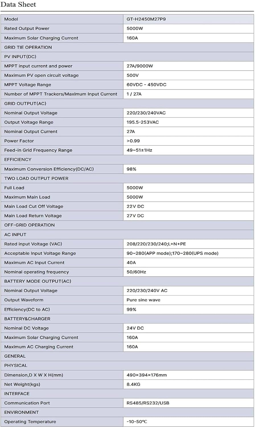
Image: A comprehensive data sheet detailing the electrical, physical, interface, and environmental specifications of the GT-H2450M27P9 Hybrid Solar Inverter.
| Parameter | Value |
|---|---|
| Model Name | GT-H2450M27P9 |
| Rated Output Power | 5000W |
| Maximum Solar Charging Current | 160A |
| MPPT Input Current and Power | 27A/9000W |
| Maximum PV Open Circuit Voltage | 500V |
| MPPT Voltage Range | 60VDC - 450VDC |
| Nominal Output Voltage (AC) | 220/230/240VAC |
| Electrical Output Waveform | Pure Sine Wave |
| Maximum Conversion Efficiency (DC/AC) | 98% |
| Nominal DC Voltage (Battery) | 24V DC |
| Item Dimensions (L x W x H) | 45L x 35W x 50H Centimeters (Product) / 490 x 394 x 176 mm (Package) |
| Item Weight | 9.5 Kilograms (Product) / 8.4 KG (Net Weight) |
| Communication Port | RS485/RS232/USB |
| Operating Temperature | -10°C to 50°C |
9. Warranty Information
This product comes with a 24-month warranty from the date of purchase. The warranty covers defects in materials and workmanship under normal use. It does not cover damage caused by improper installation, misuse, accidents, unauthorized modifications, or natural disasters. Please retain your proof of purchase for warranty claims.
10. Technical Support
For technical assistance, troubleshooting beyond this manual, or warranty inquiries, please contact our support team:
WhatsApp Support: +966561527436

Image: A graphic displaying the WhatsApp logo and the contact number +966561527436 for customer support.
Manufacturer: Shenzhen Jiesaiyuan Electricity Co. Ltd


