1. Introduction
This manual provides detailed instructions for assembling, operating, and maintaining your Cenroelon Colorful RGB DIY Digital Clock Kit (Model TJ-56-662). This kit is designed as a soldering project, offering an educational and practical experience in electronics assembly. Upon completion, the clock features time display, PM/24-hour/12-hour switching, temperature display, three alarm settings, intelligent dimming, day and week display, and a power-off memory function.

Figure 1: Assembled Colorful RGB Digital Clock Kit displaying time.

Figure 2: Assembled Digital Clock Kit displaying PM and placeholder digits.
2. Safety Information
- Always work in a well-ventilated area when soldering to avoid inhaling fumes.
- Wear appropriate personal protective equipment, such as safety glasses, to protect your eyes from solder splashes.
- Use a soldering iron stand to prevent accidental burns and keep the hot iron away from flammable materials.
- Ensure the soldering iron is properly grounded to prevent electrical shock.
- Disconnect power before making any adjustments or repairs to the assembled clock.
- Keep electronic components and tools out of reach of children.
- The working voltage is DC5V. Do not exceed this voltage to prevent damage to the circuit.
3. Package Contents
Verify that all components listed below are present in your kit before beginning assembly.

Figure 3: Overview of the electronic components included in the kit.
- PCB (Printed Circuit Board)
- 7-segment LED display modules
- Microcontroller (e.g., STC89C52RC or similar)
- Resistors (various values)
- Capacitors (electrolytic and ceramic)
- Diodes
- Transistors
- Crystal oscillator
- Buttons (Reset, Up, Set)
- DC power jack (5.5mm)
- USB power cable
- Acrylic casing components and screws
- Battery holder for CR1220 (for power-off memory)
- CR1220 battery (may be included or purchased separately)
4. Assembly Instructions
This section guides you through the soldering and assembly process. It is recommended to solder components from smallest to largest, starting with resistors and diodes, then capacitors, IC sockets, transistors, and finally larger components like the display and buttons.
4.1 Soldering Tips
- Ensure your soldering iron tip is clean and tinned.
- Heat both the component lead and the PCB pad simultaneously.
- Apply a small amount of solder to the heated joint, allowing it to flow evenly.
- Remove the solder, then the iron. The joint should be shiny and cone-shaped.
- Avoid cold solder joints (dull, lumpy) or solder bridges (solder connecting two pads).
4.2 Component Placement and Soldering Sequence
- Resistors and Diodes: Identify values using color codes or markings. Bend leads, insert into correct PCB holes, and solder. Pay attention to diode polarity (band indicates cathode).
- Capacitors: Ceramic capacitors have no polarity. Electrolytic capacitors have polarity; the longer lead is positive (+), and the shorter lead or marked side is negative (-). Match with PCB markings.
- IC Sockets: If using IC sockets, solder them first. Ensure the notch on the socket aligns with the notch on the PCB silkscreen. This prevents incorrect IC insertion.
- Transistors: Match the flat side of the transistor to the silkscreen outline on the PCB.
- Crystal Oscillator: Solder the crystal oscillator.
- Buttons and DC Jack: Solder the three control buttons (Reset, Up, Set) and the DC power jack.
- 7-Segment LED Displays: Carefully insert the LED display modules into their respective positions. Ensure they are flush with the PCB before soldering all pins.
- Battery Holder: Solder the CR1220 battery holder, observing polarity. Insert the CR1220 battery.
- Microcontroller (IC): If using an IC socket, carefully insert the microcontroller chip into the socket, ensuring the notch on the chip aligns with the notch on the socket and PCB. Bend pins slightly inward if necessary to fit.
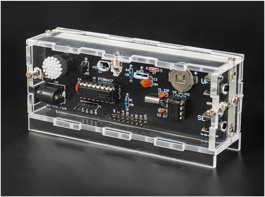
Figure 4: Assembled PCB board before final casing.

Figure 5: Circuit diagram illustrating the connections and components.
4.3 Casing Assembly
Once all components are soldered and verified, assemble the acrylic casing using the provided screws. Ensure the PCB fits snugly and the buttons align with the case openings.
5. Operating Instructions
Connect the provided USB power cable to the DC5V input jack on the clock and a suitable USB power adapter (not included). The clock will power on and display the current time or default settings.
5.1 Button Functions
- SET Button: Used to enter and confirm settings.
- UP Button: Used to increase values or cycle through options.
- RESET Button: Resets the clock.
5.2 Setting the Clock
Press the SET button to enter setting mode. Use the UP button to change values. Press SET again to confirm and move to the next setting. If no button is pressed for a period, the clock may exit setting mode automatically.

Figure 6: Function usage button diagram and setting table.
| Function | Description | Operation |
|---|---|---|
| Reset | Resets the clock. | Press and hold the SET and UP buttons for 3 seconds. |
| Setting Time | Adjusts the current time (hours and minutes). | Press SET. Use UP to adjust hours, then SET, then UP for minutes. |
| Setting Date | Adjusts the current year, month, and day. | Press SET multiple times until year flashes. Use UP to adjust. Repeat for month and day. |
| PM/12-hour/24-hour Switch | Toggles between 12-hour (with PM indicator) and 24-hour format. | Press SET until "PM" or "24H" flashes. Use UP to switch. |
| Alarm Settings (3 sets) | Sets up to three independent alarms. | Press SET until "AL1" flashes. Use UP to set alarm time, then SET to enable/disable. Repeat for AL2, AL3. |
| Intelligent Dimming | Adjusts display brightness automatically based on ambient light. | Press SET until "L1", "L2", or "L3" flashes. Use UP to select brightness level. |
| Temperature Display Unit | Switches between Celsius (°C) and Fahrenheit (°F). | Press SET until "C" or "F" flashes. Use UP to switch. |
| Color Display Mode | Cycles through various color display options (e.g., monochrome, multi-color, gradient). | Press SET until a color mode indicator flashes (e.g., "DC-1", "DC-2", "DC-3"). Use UP to cycle. |
| Sound Settings | Adjusts alarm sound or other audible feedback. | Press SET until a sound setting flashes. Use UP to adjust. |
| Time Correction | Fine-tunes the clock's accuracy. | Press SET until "DP 0" flashes. Use UP to adjust correction value. |
| Display Mode Cycle | Configures how the clock cycles through different display information (time, date, temperature). | Press SET until "DP-1", "DP-2", "DP-3", or "DP-4" flashes. Use UP to select. |
6. Maintenance
- Cleaning: Use a soft, dry cloth to clean the acrylic casing. Avoid abrasive cleaners or solvents that could damage the plastic.
- Power Supply: Always use a stable DC5V power supply. Unstable power can affect clock accuracy or damage components.
- Battery Replacement: The CR1220 battery provides power-off memory. If the clock loses time settings after being unplugged, the battery may need replacement. Carefully open the casing and replace the battery, observing polarity.
- Environment: Keep the clock away from extreme temperatures, high humidity, and direct sunlight to ensure longevity.
7. Troubleshooting
| Problem | Possible Cause | Solution |
|---|---|---|
| Clock does not power on. | No power, faulty power cable, incorrect soldering. | Check power connection. Ensure USB cable and adapter are functional. Inspect all solder joints for continuity and shorts. |
| Display is dim or uneven. | Incorrect brightness setting, faulty LED segment, cold solder joint on display. | Adjust intelligent dimming settings. Inspect LED display solder joints. |
| Clock loses time after power-off. | CR1220 battery is dead or not installed correctly. | Replace the CR1220 battery. Ensure it is inserted with correct polarity. Check battery holder solder joints. |
| Buttons do not respond. | Faulty button, incorrect soldering, button stuck. | Inspect button solder joints. Ensure buttons are not physically stuck. |
| Incorrect time or date display. | Settings are incorrect, crystal oscillator issue. | Re-enter and verify time/date settings. Check crystal oscillator solder joints. |
8. Specifications
- Product Name: Colorful Digital Clock Kit
- Product Model: TJ-56-662
- Working Voltage: DC5V (via 5.5mm DC interface)
- PCB Board Type: FR-4 Fiberglass Board
- PCB Size: 100mm x 36mm
- Functions: Time display, PM/24-hour/12-hour switching, Temperature display, Three alarm sets, Intelligent dimming, Day period display, Week display, Power-off memory function.

Figure 7: Product dimensions.
9. Support
For technical assistance or inquiries regarding your Cenroelon Colorful RGB DIY Digital Clock Kit, please refer to the seller's contact information provided at the point of purchase. Ensure you have your model number (TJ-56-662) ready when contacting support.