Introduction
This manual provides detailed instructions for the installation, operation, and maintenance of the kwbegdv DC 12-50V PWM Fan Temperature Control Speed Controller, Type A. This module is designed for automatic temperature control and speed regulation of various DC fans.
Features
- Wide Voltage Input: Supports DC 12V to 50V, compatible with various equipment.
- High Load Capacity: Maximum output current of 30A (20A for long-term use).
- Accurate PWM Control: Provides precise stepless speed and voltage regulation for stable performance.
- Intelligent Temperature Control: Automatically adjusts fan speed based on temperature, optimizing energy efficiency and noise levels.
- Broad Fan Compatibility: Works with 2-wire, 3-wire, and 4-wire fans.
- Real-time Speed Display: Monitors fan operating status for easy debugging.
- Integrated Protection: Features an onboard high-precision NTC temperature probe for intelligent cooling fan operation and protection against high temperature or overload damage (PWM output shuts down if power tube temperature exceeds 70°C).
- Output Power Indicator: Five-level indicator for output power percentage.
Setup and Installation
Important Safety Warning:
Due to the design supporting 2, 3, and 4-wire fans simultaneously, this circuit board does not have complete reverse polarity protection. Always double-check the power supply connections (+ and - poles) to ensure they are correct before powering on the device. Incorrect wiring can cause damage to the module. This device is not compatible with three-phase brushless motors, including DC air conditioning compressors.
Wiring Instructions
Refer to the wiring diagram below for proper connection of the power supply, output, and fan types.

Figure 1: Thermostat Wiring Diagram. This diagram illustrates the connections for input power, output terminals, and various fan types (2-wire, 3-wire, 4-wire).
Power Input: Connect the DC 12V-50V power supply to the "IN: DC12V~50V" terminals. Ensure correct polarity (+ and -).
Output Terminal: Connect the load (e.g., fan) to the "OUT: 30A" terminals. Ensure correct polarity.
Fan Connections:
- 2-wire fan: Connect to the 2-wire 2.54 interface or directly to the 30A output terminals, ensuring correct polarity.
- 3-wire fan: Connect to the 3-wire 2.54 interface.
- 4-wire fan: Connect to the 4-wire 2510 interface. This interface supports PWM speed control, PG speed measurement, and alarm output.
Temperature Probe: Connect the NTC thermistor temperature sensing cable to the designated probe interface.
Alarm Output: The module provides a 12V 50mA alarm output.
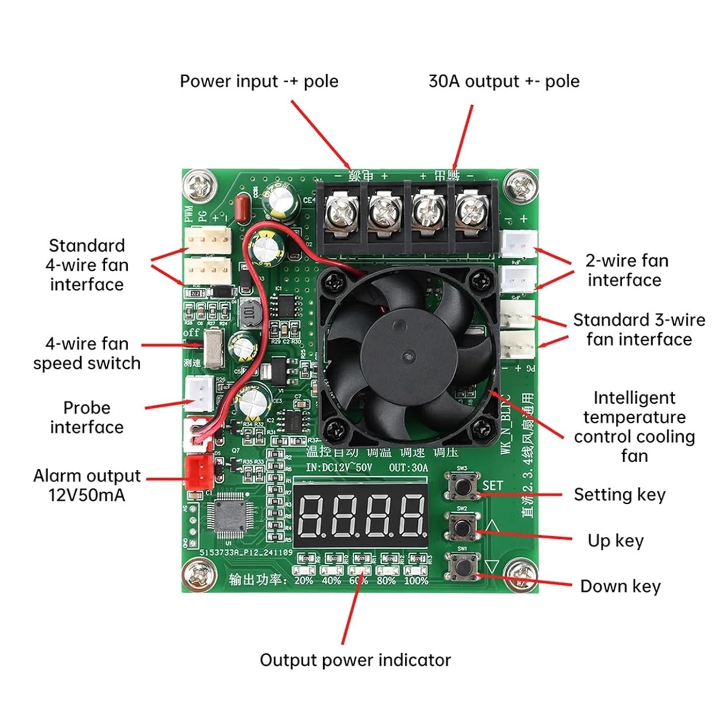
Figure 2: Component Layout and Interfaces. This image labels the power input, output, fan interfaces, probe interface, alarm output, setting keys, and output power indicators.
Operating Instructions
Basic Operation
Once properly wired and powered, the module will begin operating. The digital display shows real-time fan speed or temperature, depending on the mode.
Temperature Control Mode
The intelligent temperature control function automatically adjusts fan speed based on the temperature detected by the NTC thermistor probe. This ensures efficient cooling and reduces noise when not under heavy load.
The module is designed to protect power tubes from high temperatures. If the temperature of the MOS power tubes exceeds 70°C, the PWM output will automatically shut down to prevent damage.
Fan Compatibility Notes
- 4-wire fans: The speed display and stall fault detection function are available for one 4-wire fan connection. If two sets of the same type of 4-wire fans are connected, speed adjustment and display will work, but stall detection may not be accurate for both simultaneously.
- 2-wire and 3-wire fans: If you are not using a 4-wire fan, ensure the speed switch (labeled "OFF" near the 4-wire fan interface in Figure 2) is set to the "OFF" position. Failure to do so may trigger an "E3" alarm, preventing proper operation.
Setting Parameters
Use the "SET", "Up" (▲), and "Down" (▼) keys (visible in Figure 2) to adjust various parameters of the controller. Specific parameter settings will depend on the desired fan behavior and temperature thresholds. Consult the product's detailed parameter setting guide if available, or experiment cautiously to achieve desired performance.

Figure 3: Controller with PWM Speed Control and Display. This image highlights the PWM speed control, speed display, fault detection, and air-cooled heat dissipation features.

Figure 4: 4-wire fan PG speed measurement categories. This explains how the controller interprets speed signals from 4-wire fans and the conditions for stall detection.
Specifications
| Parameter | Value |
|---|---|
| Product Name | DC Temperature Control Automatic Speed Regulator Module |
| Input Voltage | DC 12V ~ 50V |
| Output Current (Max) | 30A (20A for long-term use) |
| Temperature Control Range | -40°C ~ 120°C |
| Temperature Control Precision | ± 0.1°C |
| Temperature Probe Model | NTC Thermistor 3950 10K (Accuracy 1%) |
| Ambient Temperature | -20°C ~ 50°C |
| Humidity | 80% (non-condensing) |
| Dimensions | Approximately 0.39 x 0.39 x 0.39 inches |
| Item Weight | Approximately 12.3 ounces (350 grams) |
| Material | Metal |
Troubleshooting
This section provides general guidance for common issues. For persistent problems, contact customer support.
- Device not powering on:
- Verify that the input voltage is within the DC 12V-50V range.
- Check all power connections for correct polarity (+ and -). Refer to the wiring diagram.
- Ensure the power supply is functioning correctly.
- Fan not spinning or incorrect speed:
- Check fan connections for correct wiring and polarity.
- Ensure the fan is compatible (2-wire, 3-wire, or 4-wire DC fan).
- If using a 2-wire or 3-wire fan, ensure the 4-wire speed switch is in the "OFF" position to avoid "E3" alarms.
- Verify that the temperature probe is correctly connected and functioning.
- Check for any error codes on the digital display.
- "E3" Alarm:
- This alarm typically indicates an issue with fan detection, especially if a 4-wire fan is expected but not connected, or if the speed switch is in the wrong position for 2/3-wire fans. Set the speed switch to "OFF" if not using a 4-wire fan.
- Overheating Protection Triggered:
- If the PWM output shuts down, it may be due to the power tube temperature exceeding 70°C. Ensure adequate ventilation around the module. Reduce the load if possible.
Maintenance
The kwbegdv DC 12-50V PWM Fan Temperature Control Speed Controller is designed for reliable operation with minimal maintenance.
- Cleaning: Periodically inspect the module for dust accumulation. Use a soft, dry brush or compressed air to gently clean the circuit board and fan to ensure proper heat dissipation.
- Connections: Regularly check all wiring connections to ensure they are secure and free from corrosion.
- Environment: Operate the module within the specified ambient temperature and humidity ranges to prolong its lifespan. Avoid exposure to moisture or extreme temperatures.
Warranty and Support
For warranty information or technical support, please refer to the documentation provided with your purchase or contact the retailer/manufacturer directly. Keep your purchase receipt as proof of purchase.