1. Introduction
This manual provides detailed instructions for the installation, operation, and maintenance of the RYRMCVPVCT JK-PB2A16S20PX4.3LCD Inverter Battery Management System (BMS). This intelligent BMS is designed for 8S to 16S Li-ion, LiFePo4, and LTO battery packs, offering robust protection and active balancing capabilities for energy storage applications. Please read this manual thoroughly before using the product to ensure safe and efficient operation.
2. Package Contents
Verify that all items listed below are included in your package:
- 1 x JK Inverter BMS Unit (Model: JK-PB2A16S20PX4.3LCD)
- 1 x 4.3-inch LCD Interface Board
- 1 x B+ Cable
- 4 x Mounting Screws
- 1 x Adapter Cable
- 1 x Trunk Interface Cable
- 1 x RJ45 Communication Cable
- 2 x Sampling Cables
- 1 x Heating Adapter Cable (if applicable to your model)
3. Key Features
The JK-PB2A16S20PX4.3LCD Inverter BMS offers a range of advanced features for optimal battery management:
- Active Balance Function: Features 2A active balancing to equalize cell voltages, enhancing battery efficiency and lifespan.
- Comprehensive Protection: Includes overcharge protection, over-discharge protection, overcurrent protection, short circuit protection, and low-temperature charging cut-off.
- Smart Communication: Supports BT (Bluetooth), RS232, RS485, and CAN communication protocols for versatile integration and monitoring.
- Dedicated Mobile APP: Utilize the JK Own Development APP for real-time battery status monitoring and BMS settings adjustment via Bluetooth.
- 4.3-inch LCD Display: Provides clear, real-time display of battery parameters such as voltage, current, state of charge, and temperature.
- Wide Battery Compatibility: Compatible with 8S to 16S configurations for Li-ion, LiFePo4, and LTO battery types.
- High Current Capacity: Designed for charge and discharge currents up to 200A.
- Common Port Design: Utilizes a common port for both charging and discharging.
- Optional Heating Function: Supports battery heating to optimize performance in cold environments.

Figure 3.1: Multiple Protection and Enhanced Safety Features. This image displays icons representing various functions such as battery information viewing, alarm features, accurate usage clock, multi-channel communication, charge/discharge data recording, current limiting for parallel connections, optional heating, and a low-voltage switch.
4. Specifications
| Parameter | Value |
|---|---|
| Model | JK-PB2A16S20PX4.3LCD |
| Battery Type Compatibility | Li-ion, LiFePo4, LTO |
| Battery String Configuration | 8S ~ 16S |
| Maximum Charge Current | 200A |
| Maximum Discharge Current | 200A |
| Active Balance Current | 2A |
| Display | 4.3-inch LCD |
| Communication Interfaces | BT, RS232, RS485, CAN |
| Protection Functions | Overcharge, Over-discharge, Overcurrent, Short Circuit, Low Temperature Charging Cut-off |
| Charge/Discharge Port | Common Port |
| Operating System Compatibility | Android or iOS (for APP) |
| Item Weight | 1000 Grams |

Figure 4.1: JK-PB2A16S20P BMS Overview. This image provides a detailed overview of the BMS module, including its physical dimensions, the interface board, and a summary of its key specifications such as communication types, supported battery types, charge/discharge current, battery string range, and balancing current.
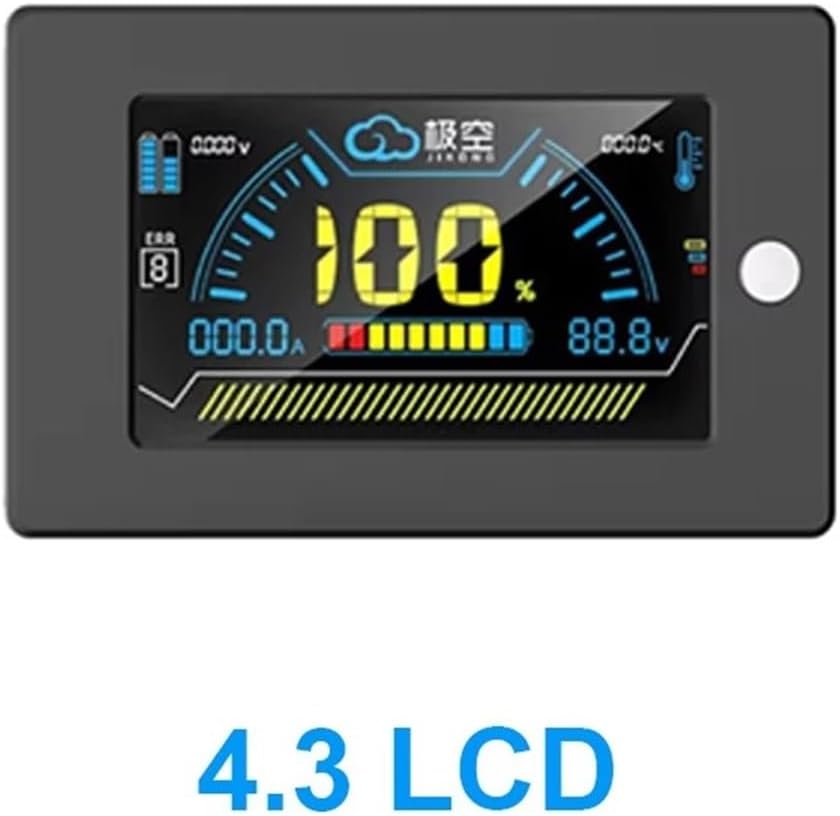
Figure 4.2: 4.3-inch LCD Display. A close-up of the 4.3-inch LCD screen, illustrating its graphical interface for displaying critical battery parameters like voltage, current, state of charge, and temperature readings.

Figure 4.3: BMS Module and LCD Display. This image shows the main BMS unit and the 4.3-inch LCD display side-by-side, indicating their connection points and overall form factor.

Figure 4.4: Exploded View of BMS Components. An exploded diagram revealing the internal structure and components of the BMS, including cooling aluminum alloy plates, flexible wiring terminals, the high-performance MCU, low internal resistance MOS, sampling lines, and the interface board.
5. Setup and Installation
Proper installation is crucial for the safe and effective operation of your BMS. Follow these steps carefully:
- Connecting all the cables: Ensure all necessary cables (sampling cables, communication cables, power cables) are prepared and correctly identified.
- Insert the cable into the BMS: Carefully connect the sampling cables to the designated ports on the BMS, ensuring correct polarity and sequence for each cell.
- Connect the B+ line, B- line, and the P- line to the battery:
- Connect the main positive (B+) cable from the battery pack to the B+ terminal on the BMS.
- Connect the main negative (B-) cable from the battery pack to the B- terminal on the BMS.
- Connect the load/charge negative (P-) cable to the P- terminal on the BMS.
- Connect the LCD Display: Attach the 4.3-inch LCD display to the BMS using the provided cable.
- Connect External Devices: Connect the inverter, electric machinery, or other loads/chargers to the appropriate terminals as shown in the wiring diagram.

Figure 5.1: Installation and Wiring Diagram. This diagram illustrates the complete wiring scheme for the BMS, showing connections from the battery pack (including individual cell sampling lines), the main B+, B-, and P- lines, and connections to an inverter, electric machinery, and the external display unit.
Important Safety Note: Always ensure that the battery pack is disconnected from any power sources before beginning installation. Double-check all wiring connections for correct polarity and secure fastening to prevent damage to the BMS or battery. Incorrect wiring can lead to severe damage or safety hazards.
6. Operating Instructions
Once installed, the BMS will begin monitoring and managing your battery pack. Here's how to operate and monitor the system:
6.1. Using the 4.3-inch LCD Display
The LCD display provides real-time information about your battery system. It typically shows:
- Total Battery Voltage
- Current (Charge/Discharge)
- State of Charge (SOC) Percentage
- Individual Cell Voltages
- Battery Temperature
- BMS Status and Error Codes
Navigate through the display menus using the buttons on the display unit (if available) to view different parameters or access settings. Refer to the display's specific user guide for detailed navigation instructions.
6.2. Using the Mobile APP (Bluetooth Communication)
The JK Inverter BMS features a dedicated mobile application for advanced monitoring and configuration. Follow these steps to connect and use the APP:
- Download the APP: Search for the "JK BMS" or "JK Inverter BMS" APP on your Android or iOS device's app store.
- Enable Bluetooth: Ensure Bluetooth is enabled on your mobile device.
- Connect to BMS: Open the APP and search for available Bluetooth devices. Select your BMS (it may appear as "JK-BMS" or a similar identifier).
- Monitor and Configure: Once connected, the APP will display detailed battery information, including individual cell voltages, temperature, current, and historical data. You can also adjust various BMS parameters and settings through the APP interface.
The APP provides a comprehensive overview and control, allowing for fine-tuning of protection thresholds and monitoring of battery health over time.
7. Maintenance
To ensure the longevity and optimal performance of your BMS, consider the following maintenance guidelines:
- Regular Inspection: Periodically inspect all wiring connections for tightness and signs of corrosion or damage.
- Cleanliness: Keep the BMS unit clean and free from dust, dirt, and moisture. Use a dry, soft cloth for cleaning.
- Environmental Conditions: Ensure the BMS operates within its specified temperature and humidity ranges. Avoid exposing it to extreme conditions.
- Firmware Updates: Check with the manufacturer or seller for any available firmware updates for the BMS, which may improve performance or add new features.
- Battery Health Monitoring: Regularly monitor battery cell voltages and temperatures via the LCD or APP to identify any anomalies early.
8. Troubleshooting
If you encounter issues with your BMS, refer to the following common troubleshooting steps:
| Problem | Possible Cause | Solution |
|---|---|---|
| BMS not powering on / LCD blank | Incorrect B+ or B- connection, low battery voltage, faulty cable. | Check main power connections. Verify battery voltage is within operating range. Inspect cables for damage. |
| No charge/discharge current | BMS in protection mode (e.g., over-discharge, overcurrent), incorrect P- connection. | Check BMS status on LCD/APP for protection triggers. Verify P- line connection. Address the cause of protection (e.g., charge battery). |
| Cell voltage imbalance | Active balancing not functioning, significant cell degradation. | Ensure balancing function is enabled (if configurable). Allow BMS time to balance. If severe, individual cell inspection may be needed. |
| Bluetooth connection issues | Bluetooth disabled, BMS out of range, APP issues. | Ensure Bluetooth is on. Move closer to BMS. Restart APP/phone. Check APP permissions. |
| BMS overheating | Excessive current, poor ventilation, high ambient temperature. | Reduce load/charge current. Ensure adequate airflow around BMS. Check ambient temperature. |
For issues not covered here, or if problems persist, please contact the manufacturer or seller for further assistance.
9. Application Scenarios
The RYRMCVPVCT JK-PB2A16S20PX4.3LCD Inverter BMS is versatile and suitable for various energy storage applications:
- Home Energy Storage Systems: Ideal for residential solar power systems or backup power solutions.
- Communication Base Stations: Provides reliable battery management for critical telecommunications infrastructure.
- Building Energy Storage: Suitable for commercial or industrial buildings requiring robust energy management.
- Industrial Equipment Backup Power: Ensures continuous operation of essential industrial machinery during power outages.

Figure 9.1: Tailor-made for Home Energy Storage Systems and Other Applications. This image depicts various environments where the BMS can be utilized, including a detailed diagram of a house with an integrated energy storage cabinet, a communication base station, a building energy storage setup, and industrial equipment.
10. Warranty and Support
Warranty information for the RYRMCVPVCT JK-PB2A16S20PX4.3LCD Inverter BMS is typically provided by the manufacturer or the point of purchase. Please refer to your purchase documentation or contact your seller for specific warranty terms and conditions.
For technical support, troubleshooting assistance, or inquiries regarding parts and service, please contact the RYRMCVPVCT customer support team or your authorized dealer. Ensure you have your product model number (JK-PB2A16S20PX4.3LCD) and purchase details available when seeking support.