1. Introduction
Welcome to the Sntieecr Electric Circuit Motor Kit and 6-in-1 STEM Kits. This comprehensive kit is designed to introduce fundamental concepts of electricity, circuits, and engineering through hands-on experimentation. It includes components for building basic electrical circuits and materials for constructing six distinct STEM projects. This manual provides essential information for safe assembly, operation, and maintenance of your kit.
2. Safety Information
Please read and understand all safety instructions before using the kit. Adult supervision is recommended for younger users.
- Voltage Recommendation: It is recommended that the voltage for the circuit components be between 1.5V and 3V.
- 3V Usage Limit: If using a 3V power source, control the usage time. The circuit should not be operated for too long, ideally within 3 minutes per session.
- Overheating Risk: Operating the circuit for 5-10 minutes continuously, especially at higher voltages, can generate heat and potentially lead to a short circuit. Allow components to cool down between uses.
- Battery Safety: Ensure batteries are inserted with correct polarity. Do not mix old and new batteries, or different types of batteries. Remove batteries if the kit will not be used for an extended period. Batteries are not included in the kit.
- Short Circuits: Avoid creating direct connections between the positive and negative terminals of the battery without a load (like a bulb or motor) in between. This can cause rapid battery discharge, overheating, and potential damage. Refer to the circuit diagrams for correct connections.
- Small Parts: This kit contains small parts which may pose a choking hazard for young children. Keep out of reach of children under 3 years old.

Figure 2.1: Illustration of correct and incorrect circuit diagrams. The top right shows a short circuit (marked with 'X'), while the bottom left shows a correct circuit with a motor and battery (marked with a checkmark). The image also details battery holder dimensions.
3. Kit Contents
Your Sntieecr Electric Circuit Motor Kit and 6-in-1 STEM Kits include the following components:

Figure 3.1: Overview of all components included in the kit.
- 1 x Instruction Manual
- 5 x Crocodile Clip Leads (various colors)
- 5 x Bulbs
- 2 x Motors
- 2 x Motor Holders
- 2 x Rocker Switches
- 3 x Propellers with 3 Vanes
- 3 x Propellers with 4 Vanes
- 1 x Buzzer Sounder
- 1 x Bulb Holder
- 1 x AA Size Battery Holder (for 1 x 1.5V battery)
- 1 x AA Size Battery Holder (for 2 x 1.5V batteries)
- Materials for 6-in-1 STEM Projects (Fiber Optic Light, Graffiti Robot, Starlight, Music Box, Windmill, Ferris Wheel)
Note: Batteries are not included and must be purchased separately.
4. Setup and Assembly
4.1. Basic Circuit Assembly
To begin experimenting with basic circuits, follow these general steps:
- Prepare Components: Gather a battery holder (with batteries inserted correctly), crocodile clip leads, a component (e.g., bulb in a holder, motor, buzzer), and a switch if desired.
- Connect Power Source: Attach one end of a crocodile clip lead to the positive (+) terminal of the battery holder and the other end to one terminal of your component (e.g., bulb holder).
- Complete the Circuit: Attach a second crocodile clip lead from the other terminal of your component to the negative (-) terminal of the battery holder.
- Add a Switch (Optional): To control the circuit, connect the switch in series with any of the components. For example, connect one lead from the battery to one terminal of the switch, then another lead from the other terminal of the switch to your component.
- Test: If all connections are secure and correct, the component should operate (bulb lights up, motor spins, buzzer sounds).

Figure 4.1: Example of a basic circuit with a bulb and buzzer.

Figure 4.2: Close-up of an illuminated bulb.
4.2. 6-in-1 STEM Projects Assembly
The kit includes materials for six distinct STEM projects. Each project comes with its own detailed assembly instructions. Refer to the individual instruction sheets provided within the kit for step-by-step guidance.
- Fiber Optic Light: Learn about light transmission.
- Graffiti Robot: Explore basic robotics and movement.
- Starlight: Understand optical imaging and projection.
- Music Box: Discover sound vibration principles.
- Windmill: Investigate wind power and mechanical motion.
- Ferris Wheel: Study gear transmission and rotational mechanics.

Figure 4.3: Example of assembly instructions for a STEM project (Windmill).
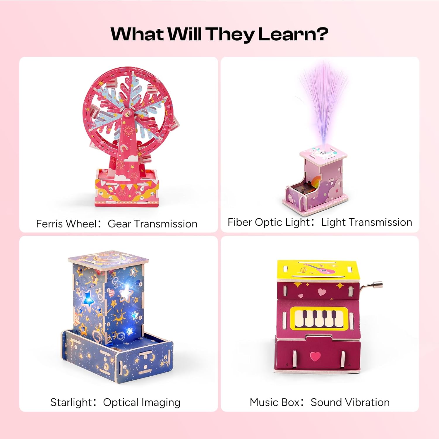
Figure 4.4: Overview of the 6-in-1 STEM projects and their learning objectives.
5. Operating Instructions
5.1. Electric Circuit Operation
Once a circuit is assembled according to the diagrams and safety guidelines, operation is straightforward:
- Power On/Off: If a switch is incorporated, use it to complete or break the circuit, turning the component on or off.
- Observe: Watch how different components behave in the circuit. For example, how does adding more bulbs affect brightness (if connected in series/parallel)?
- Experiment: Try different configurations of components (e.g., connecting two motors, a motor and a buzzer). Always ensure connections are secure and avoid short circuits.
- Duration: Adhere to the recommended usage times, especially when using 3V power, to prevent overheating.
5.2. 6-in-1 STEM Projects Operation
Each STEM project has unique operational aspects once assembled:
- Fiber Optic Light: Power on to see light transmitted through the fiber optics.
- Graffiti Robot: Insert batteries and activate to observe its movement and drawing capabilities.
- Starlight: Power on to project star patterns.
- Music Box: Wind the mechanism or activate its power source to play melodies.
- Windmill: Observe how its blades rotate, potentially with a gentle breeze or manual spin.
- Ferris Wheel: Manually rotate or power on (if applicable) to see the gear mechanism in action.

Figure 5.1: Child observing the Starlight project in operation.
6. Maintenance
Proper maintenance ensures the longevity and continued functionality of your kit:
- Storage: Store all components in a dry, cool place away from direct sunlight. Keep small parts organized to prevent loss.
- Cleaning: Wipe components with a dry, soft cloth. Do not use water or cleaning solutions on electrical parts.
- Battery Removal: Always remove batteries from holders when the kit is not in use for extended periods to prevent leakage and corrosion.
- Inspect Connections: Periodically check crocodile clip leads and other connections for wear or damage. Replace any damaged parts.
7. Troubleshooting
If you encounter issues, refer to the following troubleshooting tips:
| Problem | Possible Cause | Solution |
|---|---|---|
| Component (bulb, motor, buzzer) does not work. |
|
|
| Components get hot quickly. |
|
|
| STEM project does not function after assembly. |
|
|
8. Specifications
- Brand: Sntieecr
- Model: Electric Circuit Motor Kit and 6-in-1 STEM Kits
- ASIN: B0FY1DP4VQ
- Recommended Voltage: 1.5V - 3V
- Battery Type: AA (not included)
- Kit Contents: Circuit components (motors, bulbs, switches, leads, battery holders, buzzer, propellers), and materials for 6 STEM projects (Fiber Optic Light, Graffiti Robot, Starlight, Music Box, Windmill, Ferris Wheel).