1. Introduction
This manual provides detailed instructions for the safe and effective operation of the Generic PWM150 Dual Channel Signal Generator. This device is designed to produce adjustable Pulse Width Modulation (PWM) signals across two independent channels, suitable for applications such as servo motor control and general signal generation. Please read this manual thoroughly before use to ensure proper functionality and to prevent damage.
2. Safety Information
- Power Supply: Use only a DC power supply within the specified range of 5V to 24V. Exceeding this voltage can damage the device.
- Current Limit: Ensure the output current does not exceed 0.2A to prevent damage to the device or connected components.
- Short Circuit Protection: The device features output short-circuit protection. However, prolonged short circuits should be avoided.
- Environment: Operate the device in a dry environment, away from moisture, dust, and extreme temperatures.
- Handling: Handle the device with care to avoid physical damage.
3. Product Overview
The PWM150 is a compact dual-channel signal generator offering precise control over frequency, duty cycle, and phase. It features a clear digital display and intuitive controls for easy parameter adjustment.
3.1 Key Features
- Dual independent channels with equal performance.
- Output frequency range: 1Hz to 150KHz.
- Adjustable duty cycle: 0% to 100% (0.1% step adjustment).
- Adjustable phase: 0° to 360° (1° step, available in synchronous mode).
- Input voltage range: DC 5V-24V.
- Maximum output current: 0.2A.
- 4-digit green and 3-digit white digital tube display for frequency and duty cycle/phase.
- Rotary encoder and four-function buttons for parameter adjustment and mode switching.
- Synchronization function for linking both channels.
3.2 Device Components
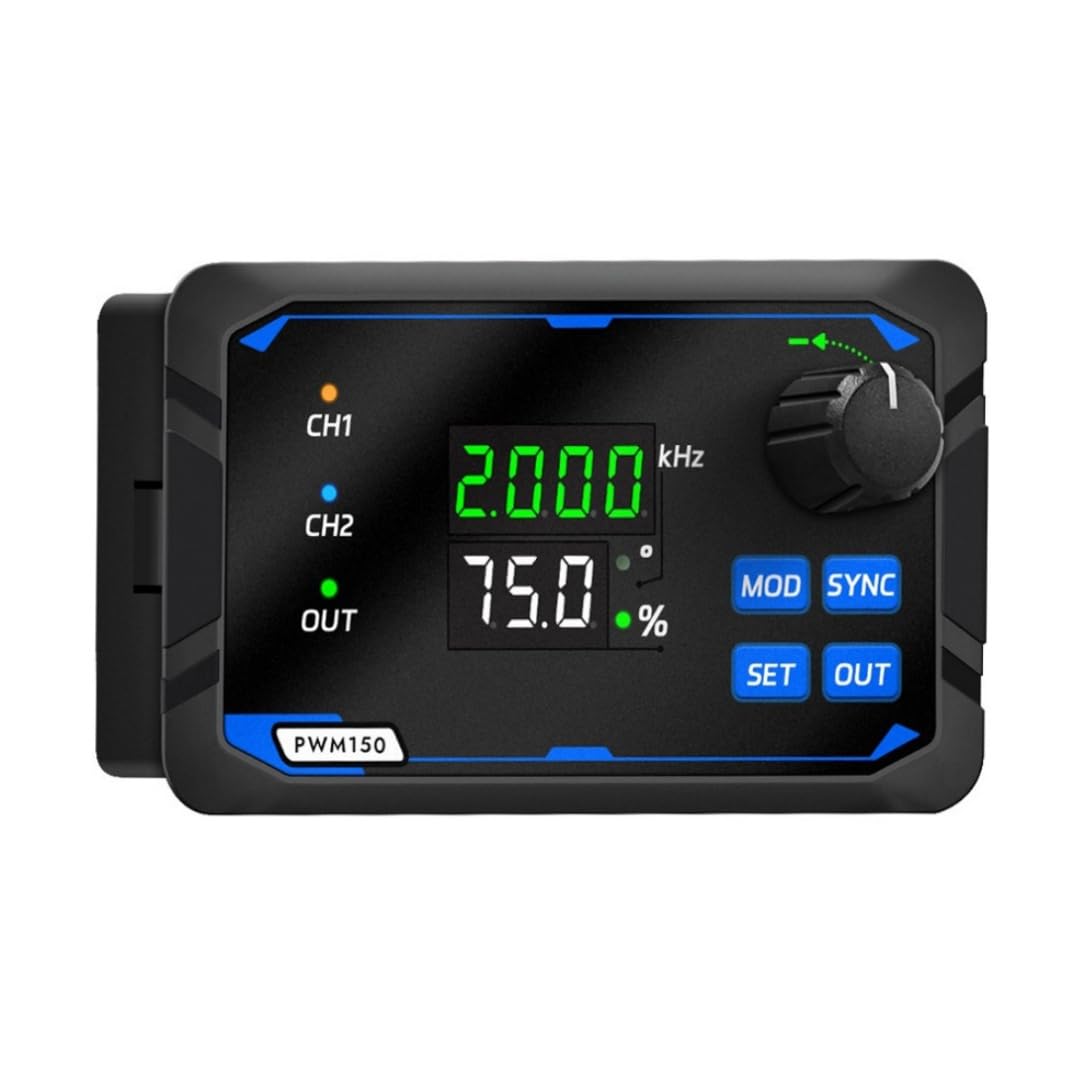
Figure 1: Front view of the PWM150 Signal Generator, showing the display, rotary encoder, and control buttons.
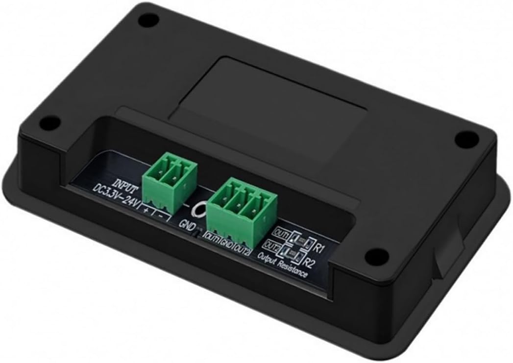
Figure 2: Rear view of the PWM150 Signal Generator, illustrating the DC power input and dual channel output terminals.

Figure 3: Detailed diagram of the PWM150 controls and indicators, including the rotary encoder, Mod key, Sync button, Set key, Out key, unit indicator lights, and three-color status lights.
- Rotary Encoder: Used for adjusting parameter values. Short press to switch between digits (flashing indicator), rotate to change the value.
- MOD Key: Switches between channel selection (CH1/CH2) or duty cycle/phase display when in sync mode.
- SYNC Button: Enables dual-channel parameter synchronization, allowing linked adjustment of frequency, duty cycle, and phase.
- SET Key: Accesses system settings, including power-on output, parameter saving/retrieval, and frequency/duty cycle upper/lower limit settings.
- OUT Key: Toggles the PWM signal output on or off. A green LED indicates output status.
- Unit Indicator Light: Indicates whether the displayed value is Phase or % duty cycle.
- Three-color Status Light: Provides clear status indication for CH1, CH2, and OUT.
- Display System: Features a 4-digit green LED for frequency (e.g., 1.200 kHz) and a 3-digit white LED for duty cycle or phase (e.g., 75.0%).
4. Setup
Follow these steps to set up your PWM150 Signal Generator:
- Power Connection: Connect a DC power supply (5V-24V) to the "INPUT" terminals on the rear of the device. Ensure correct polarity (+ to +, - to -).
- Output Connection: Connect your target device (e.g., servo motor, LED driver) to the "OUT1" and "OUT2" terminals for Channel 1 and Channel 2, respectively. Observe correct polarity and ensure the load does not exceed 0.2A.
- Initial Power On: Once connections are secure, apply power. The display should illuminate, showing default frequency and duty cycle values.

Figure 4: Rear panel of the PWM150, highlighting the INPUT (DC3.3V-24V) and OUT1/OUT2 terminals. The model number P/N: 250700002 is also visible.
5. Operating Instructions
5.1 Basic Operation
- Power On: Connect the power supply. The device will power on and display the last saved settings or default values.
- Select Channel: Press the MOD key to switch between Channel 1 (CH1) and Channel 2 (CH2). The active channel will be indicated on the display.
- Adjust Frequency: The upper green display shows the frequency. Rotate the Rotary Encoder to adjust the frequency. Short press the encoder to select which digit to adjust (the selected digit will flash).
- Adjust Duty Cycle: The lower white display shows the duty cycle (%). Press the MOD key until the duty cycle is displayed for the selected channel. Rotate the Rotary Encoder to adjust the duty cycle from 0% to 100%.
- Start/Stop Output: Press the OUT key to start or stop the PWM signal output for the currently selected channel. A green LED next to "OUT" will illuminate when the output is active.
5.2 Synchronization Mode
The PWM150 allows for synchronization of parameters between CH1 and CH2.
- Enable Sync: Press the SYNC button. The display will indicate that synchronization mode is active.
- Adjust Synchronized Parameters: In sync mode, adjustments made to frequency or duty cycle on one channel will automatically apply to the other channel.
- Adjust Phase: When in sync mode, you can adjust the phase difference between CH1 and CH2. Press the MOD key until the lower white display shows the phase (e.g., 0°). Rotate the Rotary Encoder to adjust the phase from 0° to 360°.
- Disable Sync: Press the SYNC button again to exit synchronization mode.
5.3 System Settings (SET Key)
Press the SET key to access advanced settings. Use the Rotary Encoder to navigate and adjust values, and the SET key again to confirm or exit. Refer to the on-screen prompts for specific options, which may include:
- Power-on output state (on/off).
- Saving and recalling custom parameter settings.
- Setting upper and lower limits for frequency and duty cycle.
6. Specifications
| Parameter | Value |
|---|---|
| Output Frequency Range | 1Hz - 150kHz |
| Duty Cycle Adjustment | 0% - 100% (0.1% step) |
| Phase Adjustment | 0° - 360° (1° step, synchronous mode) |
| Rise Time | 20ns |
| Output Voltage | Equal to Input Voltage (DC 5V-24V) |
| Output Current (Max) | 0.2A |
| Display System | 4-digit green (frequency) + 3-digit white (duty cycle/phase) digital tubes |
| Power Supply Mode | External DC 5V-24V |
| Dimensions | 120mm x 75mm x 50mm (approximate) |
| Model Number | PWM150 (P/N: 250700002) |
| Included Components | 1x Signal Generator |
7. Maintenance
- Cleaning: Use a soft, dry cloth to clean the device. Do not use liquid cleaners or solvents.
- Storage: Store the device in a cool, dry place when not in use.
- Inspection: Periodically check all connections for wear or damage.
8. Troubleshooting
- No Power: Ensure the DC power supply is correctly connected and within the 5V-24V range. Check the power adapter and cable.
- No Output Signal:
- Verify that the OUT key has been pressed and the green OUT LED is illuminated.
- Check output connections to the load.
- Ensure frequency and duty cycle parameters are set to valid values (not 0% duty cycle).
- Incorrect Readings/Unstable Output:
- Check for loose connections.
- Ensure the power supply is stable and providing sufficient current.
- Avoid operating in environments with strong electromagnetic interference.
- Buttons/Encoder Unresponsive: Power cycle the device. If the issue persists, contact support.
9. Warranty and Support
This Generic PWM150 Dual Channel Signal Generator comes with a 1-month warranty from the date of purchase, covering manufacturing defects. For technical support, warranty claims, or any operational questions not covered in this manual, please contact the seller or manufacturer (YiBian) directly through your purchase platform.
Please provide your ASIN (B0FXMFGCZK) and model number (PWM150, P/N: 250700002) when contacting support for faster assistance.