1. Introduction
This manual provides essential information for the proper installation, operation, and maintenance of the Generic 74HC4051 8 Channel Analog Multiplexer Selector Module. Please read this manual thoroughly before using the module to ensure safe and efficient operation.
2. Product Overview
The 74HC4051 is an 8-channel analog multiplexer/demultiplexer module designed for selecting one of eight analog inputs or outputs using digital control signals. It is commonly used in applications requiring signal routing, data acquisition, or sensor interfacing with microcontrollers. The module operates with a wide range of supply voltages and offers low ON-resistance and low leakage currents.
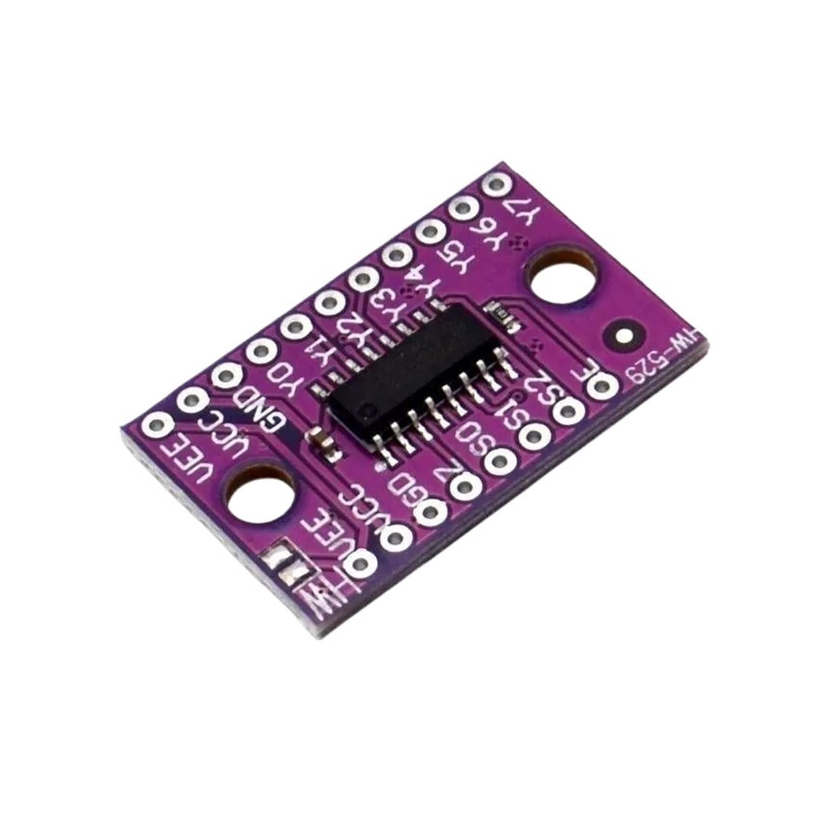
Figure 2.1: Top view of the 74HC4051 module with header pins. This image shows the main integrated circuit, various pins for power, ground, analog inputs/outputs (Y0-Y7), and digital control signals (S0, S1, S2, OE).
3. Key Features
- 8-Channel Analog Multiplexer/Demultiplexer: Allows selection of one of eight inputs to a common output, or vice-versa.
- Wide Compatibility: Designed to work with multiple systems and devices, offering seamless integration for various applications, including electronics, automotive, and industrial equipment.
- High-Quality Construction: Built with durable materials and precision engineering, ensuring reliable performance, long-lasting use, and resistance to wear, heat, or electrical interference.
- Easy Plug-and-Play Installation: Simple setup with no complex wiring required—just connect and start using it immediately for hassle-free upgrades or replacements.
- Stable & Efficient Performance: Engineered for consistent operation, delivering optimal power management, signal processing, or control functions.
- Multi-Layer Protection: Features built-in safeguards such as overcurrent protection, short-circuit prevention, and voltage stabilization for enhanced safety and durability.
4. Setup Instructions
Follow these steps to properly set up your 74HC4051 module:
- Power Supply Connection:
- Connect VCC to your positive digital supply voltage (e.g., +5V for TTL/CMOS logic).
- Connect GND to the common ground of your system.
- Connect VEE to the negative analog supply voltage (e.g., -5V for bipolar analog signals) or to GND if only unipolar analog signals are used.
- Analog Signal Connections:
- Connect your 8 analog input/output signals to pins Y0 through Y7.
- Connect the common analog input/output to pin Z.
- Digital Control Connections:
- Connect your digital control signals to pins S0, S1, and S2. These pins determine which Y-channel is connected to Z.
- Connect the Enable pin (OE or E) to GND to enable the multiplexer. If OE is high, all channels are disconnected (high impedance state).
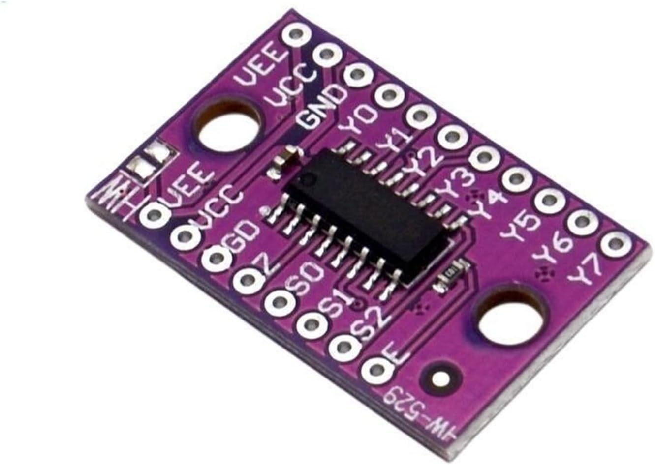
Figure 4.1: Detailed view of the 74HC4051 module pins. This image highlights the pin labels for VEE, VCC, GND, Y0-Y7, Z, S0, S1, S2, and OE, which are crucial for correct wiring.
5. Operating Instructions
The 74HC4051 module operates by selecting one of its 8 channels (Y0-Y7) to connect to the common Z pin, based on the 3-bit binary input provided to the S0, S1, and S2 control pins.
5.1. Channel Selection
To select a specific channel, apply the corresponding binary code to the S0 (Least Significant Bit), S1, and S2 (Most Significant Bit) pins. Ensure the OE (Enable) pin is held LOW (0V) to enable the multiplexer.
| S2 | S1 | S0 | Selected Channel |
|---|---|---|---|
| 0 | 0 | 0 | Y0 |
| 0 | 0 | 1 | Y1 |
| 0 | 1 | 0 | Y2 |
| 0 | 1 | 1 | Y3 |
| 1 | 0 | 0 | Y4 |
| 1 | 0 | 1 | Y5 |
| 1 | 1 | 0 | Y6 |
| 1 | 1 | 1 | Y7 |
5.2. Disabling the Multiplexer
To disconnect all channels from the Z pin, set the OE (Enable) pin to HIGH (VCC). This puts the multiplexer into a high-impedance state, effectively isolating the Z pin from all Y-channels.
6. Maintenance
The 74HC4051 module is designed for reliable operation with minimal maintenance. Observe the following guidelines:
- Keep Clean: Ensure the module is free from dust, dirt, and moisture. Use a soft, dry cloth for cleaning if necessary.
- Environmental Conditions: Operate the module within its specified operating temperature and humidity ranges to prevent damage.
- Handle with Care: Avoid physical shock or excessive force, which can damage the components or solder joints.
- Power Off Before Connecting/Disconnecting: Always disconnect power before making or changing any electrical connections to prevent short circuits or component damage.
7. Troubleshooting
If you encounter issues with your 74HC4051 module, consider the following common problems and solutions:
- No Signal Output:
- Check if the OE (Enable) pin is correctly connected to LOW (GND). If it's HIGH, the multiplexer is disabled.
- Verify all power connections (VCC, GND, VEE) are correct and stable.
- Ensure the digital control signals (S0, S1, S2) are correctly selecting the desired channel.
- Inspect for loose or incorrect wiring.
- Incorrect Signal Output:
- Double-check the binary code applied to S0, S1, S2 to ensure the correct channel is selected.
- Ensure the analog input signals are within the specified voltage range for the module.
- Check for noise or interference in the analog or digital signal lines.
- Module Not Powering On:
- Confirm that VCC and GND are connected to the correct voltage and ground.
- Check the power supply itself to ensure it is providing the correct voltage and current.
8. Specifications
The following are the technical specifications for the Generic 74HC4051 module:
| Specification | Value |
|---|---|
| Brand | Generic |
| Model Name | GFAAFBAAX |
| Model Number | GFAAFBAAX |
| ASIN | B0FXH2JKDJ |
| Type | 8 Channel Analog Multiplexer/Demultiplexer |
| Supply Voltage (VCC) | Typically +2V to +6V |
| Analog Input/Output Voltage Range | VEE to VCC |
| Operating Temperature | Not specified (typical for HC series: -40°C to +85°C) |
Note: Specific operating temperature and dissipation power values were not provided in the product description. Refer to the 74HC4051 datasheet for detailed IC specifications.
9. Warranty and Support
Specific warranty information for this Generic 74HC4051 module is not provided in the product details. For warranty claims, technical support, or further assistance, please contact the seller or manufacturer directly through your purchase platform.
For general information regarding the 74HC4051 integrated circuit, refer to the official datasheets provided by semiconductor manufacturers such as NXP, Texas Instruments, or STMicroelectronics.