Jalzdieod SMC05
Jalzdieod SMC05 Stepper/Servo Motor Pulse Controller User Manual
Model: SMC05
1. Introduction
The Jalzdieod SMC05 is an adjustable voltage regulator and pulse controller designed for precise control of stepper and servo motors. This device integrates a 1.8-inch color screen for intuitive monitoring and setup, making it suitable for various industrial applications including machinery and automation control. It supports a wide range of operating voltages and offers multiple communication options for seamless integration into existing systems.
2. Key Features
- 1.8-inch Color Screen: Provides clear display of operational parameters.
- Versatile Motor Control: Designed for stepper and servo motors with a 12-24V operating voltage range.
- High Pulse Frequency: Supports motor pulse frequencies from 1Hz to 200,000Hz for precise control.
- Multiple Outputs: Four outputs capable of driving devices under 500mA, suitable for indicators and solenoid valves.
- Extensive Inputs: Includes four limit switch inputs and three expansion key inputs for enhanced control.
- Communication Options: Modbus protocol support via serial port, Bluetooth, and 485.
- Firmware Upgrade: Compatible with PC and Android applications for firmware updates and wireless operation.
- Preset Control Modes: Offers multiple preset control modes and power-off memory.
- User-Friendly Interface: Features knob operation and shortcut buttons for ease of use.
3. Product Overview
The SMC05 controller features a compact design with a front-facing display, control knob, and four function buttons. The rear panel provides various connection terminals for power, inputs, outputs, and communication.

Figure 3.1: Front view of the SMC05 controller with its 1.8-inch color screen, control knob, and buttons (FWD, REV, SET, ENT).
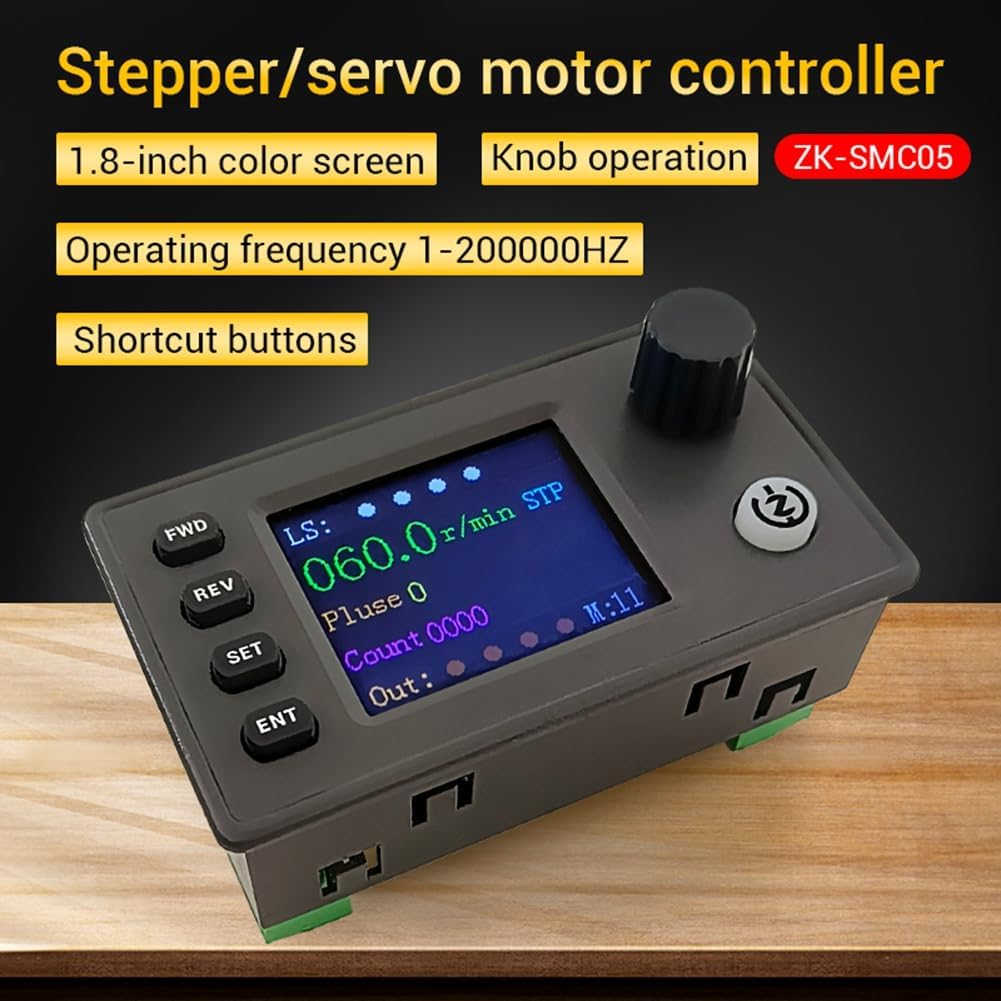
Figure 3.2: Detailed view emphasizing the controller's key features like the color screen and operating frequency range.
4. Setup and Installation
Proper installation is crucial for the optimal performance of the SMC05 controller. Follow these steps for setup and wiring.
4.1 Power Supply Connection
Connect a DC 12-24V power supply to the designated terminals on the controller. Ensure correct polarity to prevent damage.
4.2 Wiring the Extension Interface
The controller provides terminals for power input, limit switches, expansion buttons, communication, and motor drive outputs.

Figure 4.1: Overview of the extension interface and its various connection points.
4.3 Limit Switch and Output Wiring
For NPN normally open proximity switches, connect the brown wire to 24V, the blue wire to 0V, and the black wire to the limit interface terminals (X1/X2/X3/X4). The Y1-Y4 terminals provide output drive signals for devices like indicator lights or solenoid valves.

Figure 4.2: Wiring diagram for limit switches and output signals.
4.4 Mounting Dimensions
Refer to the diagram below for product dimensions and suggested hole sizes for panel mounting.

Figure 4.3: Product dimensions and suggested hole size for installation.
5. Operating Instructions
The SMC05 controller is designed for ease of operation with its intuitive display and control elements.
5.1 Display Interface
The 1.8-inch color screen displays real-time information such as motor speed (r/min), pulse count, output status, and current mode (e.g., STP for Stepper). Limit switch status (LS) is also indicated.
5.2 Button Functions
- FWD: Initiates forward motion or increases a value.
- REV: Initiates reverse motion or decreases a value.
- SET: Enters setup mode or confirms a selection.
- ENT: Confirms an entry or executes a command.
5.3 Knob Operation
The rotary knob is used for adjusting parameters, navigating menus, and fine-tuning settings on the display.
5.4 Advanced Control and Communication
The controller supports 20 different sports modes and can be upgraded via a computer. It offers Modbus protocol communication through serial port, Bluetooth, and 485 interfaces, allowing for remote control and data exchange.

Figure 5.1: PC and Android APP compatibility for advanced control and firmware updates.
6. Maintenance
To ensure the longevity and reliable operation of your SMC05 controller, observe the following maintenance guidelines:
- Cleaning: Keep the device clean and free from dust and debris. Use a soft, dry cloth for cleaning. Avoid liquid cleaners.
- Operating Environment: Operate the controller within the specified temperature range of -5°C to 60°C (non-condensing). Avoid exposure to excessive moisture, direct sunlight, or corrosive environments.
- Connections: Periodically check all wiring connections to ensure they are secure and free from corrosion.
7. Troubleshooting
If you encounter issues with your SMC05 controller, consider the following basic troubleshooting steps:
- No Power: Verify that the power supply is correctly connected and providing the specified DC 12-24V. Check power cables and connections.
- Motor Not Responding: Ensure all motor wiring is correct and secure. Check the pulse frequency settings and motor mode.
- Incorrect Output: Confirm that output wiring (Y1-Y4) is correct and that the connected devices are functioning properly.
- Communication Issues: Check serial port, Bluetooth, or 485 connections. Ensure correct protocol settings and device addresses.
- Display Malfunction: If the screen is blank or displaying errors, power cycle the device. If the issue persists, contact support.
8. Specifications
| Brand | Jalzdieod |
| Model | SMC05 |
| Operating Voltage | DC 12-24V |
| Operating Frequency | 1Hz - 200,000Hz |
| Outputs | 4 (under 500mA) |
| Inputs | 4 Limit Switch, 3 Expansion Key |
| Display | 1.8-inch Color Screen |
| Communication | Modbus (Serial, Bluetooth, 485) |
| Operating Environment | -5°C to 60°C (non-condensing) |
| Dimensions | 11 x 7 x 6 cm (Parcel) |
| Weight | 133.5 g |
9. Warranty and Support
Specific warranty terms and detailed support contact information are not provided in the product details. Please refer to your purchase documentation or contact the retailer for information regarding warranty coverage and technical support.
10. Important Disclaimers
Electronic module products require a certain electronic foundation and careful reading of product instructions before use. This product is not designed for medical, life-saving, or life-sustaining purposes, and should not be used in dangerous places such as coal mines and oil depots. The manufacturer does not guarantee any liability, and the profit margin of the product is low. The user's operational ability and usage scenarios vary greatly. No electronic device can be foolproof. The equipment owner should take corresponding protective measures and risk management plans. If any personal or property damage is directly or indirectly caused by this equipment, the company is not responsible for compensation.
Ask a question about this manual
Ask about setup, troubleshooting, compatibility, parts, safety, or missing instructions. Manuals+ will review the question and use this page’s manual context to help answer it.