TS TST GRP LLC R004
TST Electric Bike R004 User Manual
Model: R004 | Brand: TS TST GRP LLC
1. Introduction
This manual provides essential information for the safe assembly, operation, and maintenance of your TST Electric Bike R004. Please read it thoroughly before your first ride and keep it for future reference. Proper understanding and adherence to these instructions will ensure optimal performance and longevity of your e-bike.

Figure 1: TST Electric Bike R004 Overview
2. Important Safety Warnings
- Always wear a helmet and appropriate safety gear when riding.
- Ensure all components are securely fastened before each ride.
- Users under 16 years of age should be accompanied by an adult.
- Familiarize yourself with local e-bike regulations and traffic laws.
- Regularly check tire pressure, brake function, and battery charge.
- Avoid riding in extreme weather conditions or on excessively rough terrain if unfamiliar with the bike's capabilities.
3. Package Contents
Your TST Electric Bike R004 package includes the following items:
- TST Electric Bike (partially assembled)
- 48V 15Ah Removable Battery (UL certified)
- Battery Charger
- Front Fender
- Pedals (Left and Right)
- Headlight
- Rear Rack
- Tool Kit (Hex keys, wrenches, screwdriver)
- User Manual
4. Assembly Instructions
The TST Electric Bike R004 is 90% pre-assembled. Follow these steps to complete the assembly:
4.1. Inspect Packaged Accessories
Before starting, carefully inspect all packaged accessories to ensure all parts are present and undamaged.
Video 1: Inspecting Packaged Accessories
4.2. Install the Front Wheel
- Remove the front fork guard and the brake pad.
- Assemble the quick release rod with washers and nuts in the correct order.
- Install the front wheel onto the fork, ensuring the disc brake rotor is fully seated within the caliper.
- Install the safety hook and tighten the nuts securely.
Video 2: Front Wheel Installation
4.3. Install the Kickstand
- Align the kickstand with the mounting holes on the bike frame.
- Secure the kickstand using the provided screws and hex key.
Video 3: Kickstand Installation
4.4. Install the Front Fender
- Remove the three screws from the front fork.
- Insert the fender and secure it by replacing the screws.
Video 4: Front Fender Installation
4.5. Install the Handlebars
- Loosen the seat tube screws and remove the aluminum top cap.
- Rotate the seat tube 180 degrees horizontally and then replace it.
- Unscrew the seat tube screws and install the handlebars.
- Pre-secure the handlebars, then adjust the vertical angle and tighten the seat tube screws.
- After adjusting the horizontal angle, tighten the screws on the back of the seat tube.
Video 5: Handlebar Installation
4.6. Install the Saddle
- Remove screws from the accessory package and insert washers on the screws.
- Install the taillight bracket.
- Use a 5mm hex key and a 10mm wrench to tighten the screws.
- Place the saddle on the frame, align the mounting tabs, and tighten the screws with a socket tool.
- Align the red connector on the front light with the red connector on the display marked with an arrow and push them together firmly.
Video 6: Saddle Installation
4.7. Install the Headlights
- Use a 14mm wrench to remove the screws and foam pads from both sides of the front light.
- Place the front light with the foam pads between the brackets and the light, then tighten the screws.
- Align the red connector on the front light with the red connector on the display marked with an arrow and push them together firmly.
Video 7: Headlight Installation
4.8. Install the Foot Pedals
- Note that 'L' stands for left and 'R' stands for right on the pedals.
- Tighten the right pedal clockwise and the left pedal counterclockwise.
Video 8: Foot Pedal Installation
5. Initial Setup
5.1. Battery Installation and Charging
Ensure the 48V 15Ah removable battery is securely installed in its compartment. Charge the battery fully before your first ride. The battery is UL certified for safety.
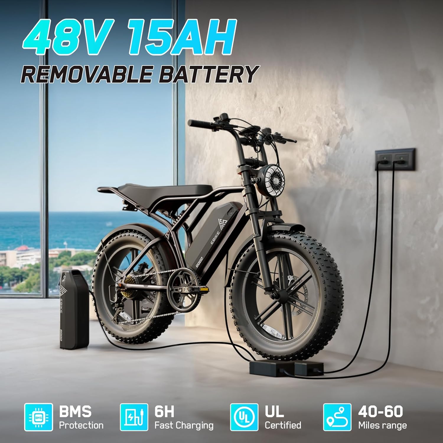
Figure 2: Removable Battery and Charging
5.2. Display Settings and Speed Limit Removal
To access instrument settings, press the "+" and "-" buttons simultaneously. Navigate to "P08" by repeatedly pressing "+". To change the speed limit, press the center power button to select 'Change', then press "+" to increase the speed from 32 to 100. Press the power button again to confirm and save the change. Finally, press "+" and "-" simultaneously to exit the interface. The speed limit will now be removed.
Video 9: Removing Speed Limits
6. Operating Instructions
6.1. Power On/Off
To power on the bike, ensure the battery is installed and turned on. Then, long-press the start button on the handlebar display until the screen lights up.
6.2. Riding Modes
The TST Electric Bike R004 features 3 working modes:
- Electric Mode: Pure electric power using the throttle.
- Assisted Mode (PAS): Pedal-assist system, providing motor assistance as you pedal.
- Ordinary Cycling Mode: Pedal without motor assistance.

Figure 3: All-Terrain Fat Tires and Riding Modes
6.3. Gear Shifting
The bike is equipped with professional 7-speed gears. Use the twist grip shifter on the handlebars to change gears according to terrain and desired speed.
6.4. Braking
The bike features mechanical disc brakes for strong and reliable stopping power. Always apply brakes smoothly and anticipate stops.

Figure 4: Headlight and Taillight for Safety
7. Maintenance
- Tire Pressure: Check tire pressure regularly and maintain it within the recommended range for optimal performance and safety.
- Brakes: Inspect brake pads and rotors for wear. Adjust brake cables as needed to ensure responsive braking.
- Chain: Keep the chain clean and lubricated to prevent rust and ensure smooth operation.
- Battery: Store the battery in a cool, dry place and charge it regularly, even when not in use, to prolong its lifespan.
- General Inspection: Periodically check all nuts, bolts, and connections for tightness.
8. Troubleshooting
| Problem | Possible Cause | Solution |
|---|---|---|
| Bike does not power on | Battery not charged or not properly installed. | Ensure battery is fully charged and securely seated. Check battery power switch. |
| Motor not assisting | PAS level too low or throttle not engaged. | Increase PAS level on display. Ensure throttle is engaged (if applicable). Check motor connections. |
| Brakes feel weak | Worn brake pads or loose cables. | Inspect and replace worn brake pads. Adjust brake cable tension. |
| Unusual noises | Loose components or dry chain. | Check all fasteners for tightness. Lubricate the chain. |
9. Specifications
| Feature | Detail |
|---|---|
| Model Name | R004 |
| Bike Type | Electric Bike |
| Age Range | Adult |
| Motor | 750W (1500W Peak) Brushless Hub Motor, 90 Nm Torque |
| Top Speed | 28 MPH |
| Battery | 48V 15Ah Removable Lithium Battery (UL Certified) |
| Charging Time | 6-7 hours |
| Range | 40 miles (throttle mode), 50-60 miles (PAS mode) |
| Wheel Size | 20 Inches (20"x 4" Fat Tires) |
| Frame Material | Aluminum |
| Suspension Type | Dual (Front and Rear Hydraulic Suspension) |
| Number of Speeds | 7-Speed Gears |
| Brake Style | Mechanical Disc Brakes |
| Special Feature | LCD-Display |
| Bicycle Weight | 66 lbs |
| Maximum Load | 450 lbs |
10. Warranty and Support
Your TST Electric Bike R004 comes with a 180-day limited warranty. For any questions, technical support, or warranty claims, please contact:
- Email: support-ebike@tstebike.com
- Phone: +1 (626) 878-4885 (Monday-Friday: 9:00 AM - 5:30 PM PST)
Please have your model number (R004) and purchase date ready when contacting support.
Related Documents - R004
 |
FEIG TST FUZ2 Controller: Assembly, Installation, and Operation Manual Detailed assembly instructions for the FEIG TST FUZ2 door controller, covering installation, commissioning, and operation for industrial and commercial intelligent door management systems. Includes safety guidelines and technical specifications for various TST FUZ2 variants. |
 |
Manual de Instalación FEIG ELECTRONIC TST FUZ2 Manual de instalación para la unidad de control de puerta FEIG ELECTRONIC TST FUZ2, detallando montaje, configuración y uso seguro para sistemas industriales y comerciales. |
 |
FEIG TST WUE2 Assembly Instructions: Installation, Commissioning, and Maintenance Guide Comprehensive assembly, installation, commissioning, utilization, and maintenance instructions for the FEIG TST WUE2 door controller, an electronic control system for industrial and commercial doors. |
 |
TST 507 Series Wireless Tire Pressure and Temperature Monitoring System Installation Manual Comprehensive installation manual for the TST 507 Series Wireless Tire Pressure and Temperature Monitoring System (TPMS). Covers setup, sensor pairing, display controls, alarms, troubleshooting, and specifications for TST TPMS products. |
 |
TST 507 Series Wireless TPMS Installation Manual Installation guide for the TST 507 Series Wireless Tire Pressure and Temperature Monitoring System (TPMS). Covers setup, sensor programming, display configuration, alerts, troubleshooting, and specifications for vehicles and trailers. |
 |
TST 507 Series TPMS: Installation Manual for Wireless Tire Pressure and Temperature Monitoring System Learn how to install and use the TST 507 Series Wireless Tire Pressure and Temperature Monitoring System (TPMS) with this comprehensive installation manual. Monitor tire pressure and temperature for RVs, motorhomes, trucks, and trailers. |