
1. Introduction
This manual provides comprehensive instructions for the installation, operation, maintenance, and troubleshooting of the DewinLVD VFD (Variable Frequency Drive) Frequency Converter. This device is designed to control the speed of standard AC motors by adjusting the frequency and voltage of the power supplied to the motor. Please read this manual thoroughly before operating the device to ensure safe and efficient use.
2. Safety Information
WARNING: Read the user manual before operation. Risk of electrical shock. Wait 10 minutes after removing power to output terminals. Do not connect AC power to output terminals U/T1, V/T2, W/T3.
- Always ensure the power supply is disconnected before performing any installation, wiring, or maintenance.
- Allow sufficient time for capacitors to discharge after power-off before touching terminals.
- Only qualified personnel should install, operate, and maintain this equipment.
- Ensure proper grounding to prevent electrical shock.
- Do not operate the VFD in environments with excessive dust, corrosive gases, or direct moisture.
- This device is suitable for standard AC motors; asymmetrical loads are not supported.
3. Product Overview
3.1 Key Features
- High-Quality Double-Layer Board: Features a smart double-layer board (power board + motherboard) for stable, high-speed processing.
- Intuitive Digital Display: Large buttons ensure easy operation, and the digital display shows real-time data clearly.
- Multiple Control Algorithms: Supports VF control for asynchronous motors, open-loop current vector control, standard open-loop control for permanent magnet synchronous motors, and open-loop vector control.
- High Performance: Provides a starting torque of 150% at 0.5 Hz (sensorless vector control), achieving high torque, high precision, wide speed control, and high power.
- Fast Current Limiting Function: Quickly limits current exceeding the protection threshold, preventing frequent trips due to sudden load interruptions or interference.
- Robust Cooling System: A high-speed fan with a special air duct ensures efficient heat dissipation, low noise, and stable operation.
- High Security & Durability: Constructed with flame-retardant ABS material, offering impact and heat resistance.
- Easy Installation: Compact size with a removable front panel and screw terminals for cable connection.
- Torque Limitation: Automatically adjusts within the preset maximum torque range when mechanical torque is exceeded, balancing efficiency and safety.
3.2 Component Identification

Figure 3.2.1: Front view of the DewinLVD VFD Frequency Converter, showing the digital display and control buttons.
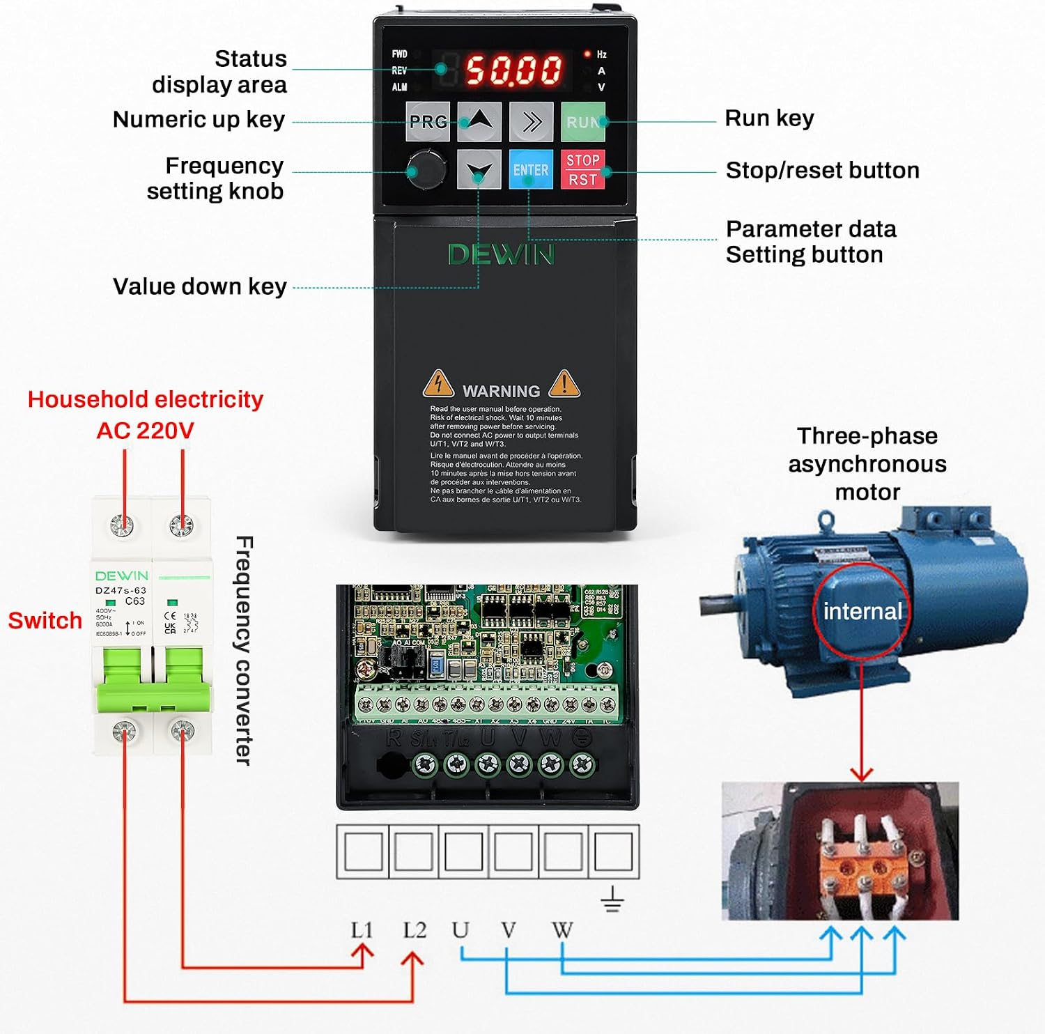
Figure 3.2.2: Detailed view of the control panel with labels for Status display area, Numeric up key, Frequency setting knob, Value down key, Run key, Stop/reset button, and Parameter data Setting button.

Figure 3.2.3: Rear view of the VFD, highlighting the integrated cooling fan for efficient heat dissipation. The product label shows model MS500-2S-2.2G, Power 2.2KW, Input 1PH AC220V 50/60Hz, Output 3PH AC220V 0-320Hz 10A.
4. Specifications
| Specification | Value |
|---|---|
| Brand | DewinLVD |
| Model Number | DewinLVD205 (MS500-2S-2.2G) |
| Wattage | 2200 Watts |
| Input Rated Voltage | Single-phase 220 Volts (AC) |
| Input Rated Frequency | 50/60 Hz |
| Output Rated Voltage | Three-phase 220 Volts (AC) |
| Output Frequency Range | 0 - 320 Hz (Low frequency mode) |
| Rated Output Current | 10 Amps |
| Peak Output Power | 2300 Watts |
| Electrical Output Waveform | Pure Sine Wave |
| Product Dimensions (L x W x H) | 11.5 x 14.2 x 7.3 cm (4.5 x 5.6 x 2.9 inches) |
| Material | Flame Retardant ABS Plastic |
| Installation Method | Wall-mounted |
| Protection Level | IP20 |
| Cooling Method | Cooling Fan |
| Country of Origin | China |

Figure 4.1: Visual representation of VFD dimensions and key specifications.
5. Installation
5.1 Physical Dimensions
The VFD has compact dimensions for easy integration into various setups. Refer to Figure 4.1 for detailed measurements.
- Length: 11.5 cm
- Width: 14.2 cm
- Height: 7.3 cm
5.2 Wiring Diagrams
Proper wiring is crucial for safe and correct operation. Ensure all connections are secure and follow local electrical codes.

Figure 5.2.1: Basic wiring diagram for connecting a single-phase 220V power supply (via a breaker) to the VFD, and then to a three-phase motor. Includes ground wire connection.

Figure 5.2.2: Detailed operational wiring diagram showing power input (R, S, T/L1, L2), multi-function input terminals (X1-X4, COM), external keyboard interface, potentiometer connection for analog input (A1), analog output (AO1), RS485 communication terminals (485+, 485-), and relay output (TA, TC).
Wiring Terminals:
- L1, L2: Single-phase 220V AC input.
- U, V, W: Three-phase 220V AC output to the motor.
- Ground Symbol: Earth ground connection.
- X1-X4, COM: Multi-function input terminals for external control signals.
- A1, 10V, GND: Analog input for potentiometer or other analog control signals (0-10V, 0-20mA).
- AO1, GND: Analog output.
- 485+, 485-: RS485 communication interface.
- TA, TC: Relay output terminals.
6. Operation
6.1 Control Panel Functions
The VFD features an intuitive control panel for easy operation and parameter setting.
- Digital Display: Shows status, frequency, voltage, current, and parameter values.
- PRG (Program) Key: Enters/exits parameter setting mode.
- Up/Down Arrow Keys: Adjust values or navigate through menus.
- ENTER Key: Confirms selections or enters sub-menus.
- RUN Key: Starts motor operation.
- STOP/RST (Reset) Key: Stops motor operation or resets alarms.
- Frequency Setting Knob: Adjusts the output frequency.
6.2 Basic Operation
- Power On: Connect the VFD to the single-phase 220V AC power supply. The digital display will light up.
- Set Frequency: Use the Frequency Setting Knob or the Up/Down arrow keys to set the desired output frequency.
- Start Motor: Press the RUN key to start the motor. The display will show the operating frequency.
- Stop Motor: Press the STOP/RST key to stop the motor.
- Parameter Adjustment: Press the PRG key to enter parameter setting mode. Use the arrow keys to navigate and ENTER to select and confirm parameters.
7. Applications
The DewinLVD VFD Frequency Converter is versatile and suitable for a wide range of industrial and professional applications requiring precise motor speed control.

Figure 7.1: Examples of common applications for the VFD.
- Fans
- Water Pumps
- Oil Pumping Presses
- Compressors
- Conveyor Belts
- Injection Molding Machines
- Crushers
- Mixers
- Ball Mills
- Other industrial equipment requiring motor speed control.
8. Maintenance
Regular maintenance ensures the longevity and optimal performance of your VFD.
- Cooling Fan: Periodically check the cooling fan for dust accumulation. Clean gently with compressed air if necessary to ensure efficient heat dissipation.
- Environmental Conditions: Ensure the VFD is operated in a clean, dry environment, free from excessive dust, moisture, and corrosive substances.
- Connections: Regularly inspect all wiring connections for tightness and signs of wear or corrosion.
- Housing: The flame-retardant ABS material is durable, but avoid exposing the unit to harsh chemicals or extreme physical impact.

Figure 8.1: Highlights of the high-speed fan, flame-retardant ABS material, and compact size contributing to maintenance and durability.
9. Troubleshooting
The VFD is equipped with several protection features to ensure safe operation. If an error occurs, the display may show an error code. Refer to the full product manual for a complete list of error codes and their remedies.
9.1 Protection Features

Figure 9.1.1: Icons representing various protection features integrated into the VFD.
- Undervoltage Protection: Protects against insufficient input voltage.
- Overvoltage Protection: Safeguards against excessive input voltage.
- Overcurrent Protection: Limits current to prevent damage from excessive load.
- Overload Protection: Prevents damage due to prolonged excessive load.
- Short Circuit Protection: Detects and reacts to short circuits in the output.
- Phase Loss Protection: Monitors for loss of a phase in the input or output.
- Overheating Protection: Shuts down the unit if internal temperatures become too high.
- Ground Protection: Ensures safety in case of ground faults.
- Stall Protection: Prevents motor damage from stalling conditions.
9.2 Fast Current Limiting
The VFD's fast current limiting function rapidly restricts current that exceeds the protection threshold. This prevents frequent trips caused by sudden load changes or interference, thereby protecting the integrity of connected devices.
9.3 Torque Limitation
When the maximum mechanical torque is exceeded, the VFD automatically adjusts within the preset maximum torque range. This feature helps to prevent mechanical damage and ensures a balance between operational efficiency and device safety.
10. Warranty and Support
Information regarding specific warranty terms and conditions for the DewinLVD VFD Frequency Converter is not available in this document. For warranty claims, technical support, or spare parts inquiries, please contact your retailer or the manufacturer directly.
- Spare Parts Availability: Information not available.
- Software Updates: Information not available.