1. Introduction
This manual provides detailed instructions for the installation, configuration, and maintenance of your Ouyniei ZSUS X99-8D4 Motherboard. This motherboard is designed to support LGA2011-3 processors, DDR4 memory, and NVMe M.2 storage, offering a robust platform for various computing needs. Please read this manual thoroughly before proceeding with installation to ensure proper setup and operation.
2. Safety Information
Always observe the following safety precautions when handling computer components:
- Electrostatic Discharge (ESD) Prevention: Always wear an anti-static wrist strap or frequently touch a grounded metal object before handling components to prevent ESD damage.
- Power Disconnection: Ensure the power supply is disconnected from the wall outlet before installing or removing any components.
- Component Handling: Handle components by their edges. Avoid touching pins, contacts, or circuit boards directly.
- Ventilation: Ensure adequate ventilation within your PC case to prevent overheating.
- Tool Usage: Use appropriate tools and avoid excessive force during installation.
3. Package Contents
Verify that all items are present in your package. If any item is damaged or missing, contact your retailer.
- Ouyniei ZSUS X99-8D4 Motherboard
- I/O Shield
- SATA Data Cable
- User Manual (this document)

Figure 3.1: Included I/O Shield and SATA Cable. The image displays the rear I/O panel of the motherboard, a separate I/O shield, and a black SATA data cable, which are typically included accessories.
4. Motherboard Layout
Familiarize yourself with the various components and connectors on the motherboard before installation.

Figure 4.1: ZSUS X99-8D4 Motherboard Component Layout. This image provides an overhead view of the motherboard with key components and connectors labeled, including the CPU socket, RAM slots, PCIe slots, SATA ports, USB headers, and power connectors.
- LGA 2011-3 CPU Socket: Central socket for Intel Xeon E5 V3/V4 processors.
- DDR4 Memory Slots (x4): Supports DDR4 RAM modules.
- PCI Express x16 Slot (x1): For graphics cards.
- PCI Express x1 Slot (x1): For expansion cards.
- NVMe M.2 Slot: For high-speed M.2 SSDs.
- SATA 2.0 Ports (x4): For traditional SATA storage devices.
- 24-pin ATX Power Connector: Main power input for the motherboard.
- 8-pin EPS/CPU Power Connector: Provides power to the CPU.
- 4-pin CPU Fan Headers (x2): For CPU cooling fans.
- USB 2.0 Headers: For front panel USB ports.
- Front Panel Audio Header: For front panel audio jacks.
- Gigabit Ethernet Port: For network connectivity.
- USB 2.0 Ports (x6): Rear panel USB ports.
- PS/2 Ports (x2): For legacy keyboard and mouse.
- Audio Jacks (x3): Rear panel audio output/input.
5. Setup and Installation
Follow these steps to install your motherboard and components.
5.1. Installing the CPU
- Locate the LGA 2011-3 socket on the motherboard.
- Gently push down the load lever and pull it away from the socket to open the CPU retention frame.
- Carefully align the CPU (e.g., Xeon E5 2650 V4) with the socket, ensuring the gold triangle on the CPU matches the triangle on the socket. Do not force the CPU into the socket.
- Lower the retention frame over the CPU and push the load lever back into its locked position.
- Apply a thin, even layer of thermal paste to the top of the CPU.
- Install the CPU cooler according to its manufacturer's instructions, ensuring it is securely fastened and connected to the appropriate CPU fan header (e.g., 4-pin CPU FAN).
5.2. Installing Memory (RAM)
- Open the clips at both ends of the DDR4 memory slots.
- Align the notch on the DDR4 memory module with the key in the memory slot.
- Insert the memory module firmly into the slot until the clips snap into place. Ensure both clips are fully closed.
- For optimal performance, refer to your CPU and memory specifications for recommended dual-channel or quad-channel configurations.
5.3. Installing Storage Devices
5.3.1. NVMe M.2 SSD Installation
- Locate the NVMe M.2 slot on the motherboard.
- Remove the M.2 standoff screw.
- Insert the M.2 SSD into the slot at a 30-degree angle.
- Gently push down the SSD and secure it with the standoff screw.
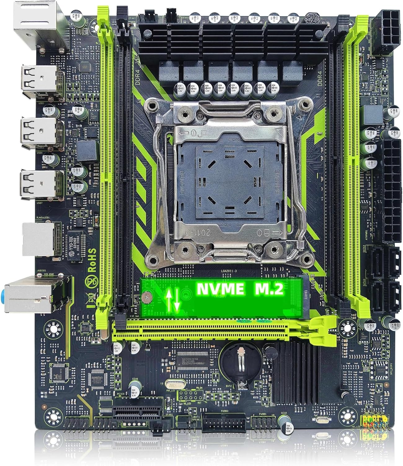
Figure 5.1: NVMe M.2 Slot. This image shows the motherboard with the NVMe M.2 slot prominently highlighted, indicating its location for SSD installation.
5.3.2. SATA Device Installation
- Connect one end of the SATA data cable to a SATA 2.0 port on the motherboard.
- Connect the other end of the SATA data cable to your SATA hard drive or SSD.
- Connect a SATA power cable from your power supply to the SATA device.
5.4. Installing Expansion Cards (PCIe)
- Align your graphics card or other PCIe expansion card with the PCIe x16 or PCIe x1 slot.
- Press down firmly until the card is seated correctly in the slot and the retention clip (if present) locks into place.
- Secure the card to your PC case with a screw.
5.5. Connecting Power Supply
- Connect the 24-pin ATX power cable from your power supply to the 24-pin connector on the motherboard.
- Connect the 8-pin EPS/CPU power cable from your power supply to the 8-pin connector near the CPU socket.
5.6. Connecting Front Panel Cables
Connect the cables from your PC case's front panel (USB, audio, power button, reset button, HDD LED, power LED) to the corresponding headers on the motherboard. Refer to the motherboard layout diagram (Figure 4.1) for header locations.
6. Operating Instructions
6.1. First Boot
- After completing all hardware installations, connect your monitor, keyboard, and mouse.
- Connect the power supply to a wall outlet and turn on the power supply switch.
- Press the power button on your PC case.
- The system should power on and display the BIOS/UEFI splash screen.
6.2. BIOS/UEFI Setup
During startup, press the designated key (usually DEL or F2) to enter the BIOS/UEFI setup utility. Here you can configure system settings such as boot order, date/time, and hardware parameters. Save changes before exiting.
6.3. Operating System Installation
Insert your operating system installation media (USB drive or DVD) and follow the on-screen prompts to install your preferred operating system. Ensure all necessary drivers are installed after the OS installation for optimal performance.
7. Maintenance
Regular maintenance helps ensure the longevity and stable operation of your motherboard.
- Cleaning: Periodically clean dust from inside your PC case, especially from fans and heatsinks, using compressed air. Ensure the system is powered off and unplugged before cleaning.
- BIOS Updates: Check the manufacturer's website for BIOS updates. BIOS updates can improve system stability, compatibility, and performance. Follow the update instructions carefully to avoid system damage.
- Driver Updates: Keep your device drivers (chipset, LAN, audio, graphics) updated to ensure optimal performance and compatibility.
8. Troubleshooting
If you encounter issues, refer to the following common troubleshooting steps:
- No Power: Ensure all power cables (24-pin ATX, 8-pin EPS) are securely connected. Check the power supply switch and wall outlet.
- No Display: Verify that the graphics card is properly seated in the PCIe slot and connected to the monitor. Ensure the monitor is powered on and set to the correct input.
- System Instability/Crashes: Check RAM modules for proper seating. Test memory with diagnostic tools. Ensure CPU cooler is properly installed and thermal paste is applied. Check for overheating.
- Boot Device Not Found: Verify that your storage device (SSD/HDD) is correctly connected (power and data cables). Check BIOS settings for correct boot order and detection of the storage device.
- Peripheral Issues: If USB devices or other peripherals are not working, try different ports. Ensure drivers are installed.
9. Specifications
Detailed technical specifications for the Ouyniei ZSUS X99-8D4 Motherboard:

Figure 9.1: Motherboard Dimensions. This image illustrates the physical dimensions of the motherboard, showing a width of 215mm and a height of 190mm.
| Feature | Specification |
|---|---|
| Model | ZSUS X99-8D4 |
| Form Factor | ATX (215mm x 190mm) |
| CPU Socket | LGA 2011-3 |
| Supported CPUs | Intel Xeon E5 V3/V4 Series (e.g., E5 2650 V4) |
| Chipset | P55 |
| Memory Slots | 4 x DDR4 DIMM slots |
| Memory Type | DDR4 |
| Max Memory Capacity | 128 GB |
| PCIe Slots | 1 x PCIe x16 (PCI-E 3.0), 1 x PCIe x1 |
| Storage Interface | 1 x M.2 (NVMe, 2280 support), 4 x SATA 2.0 |
| LAN | 1 x RJ45 (1000Mbps) |
| Rear I/O Ports | 6 x USB 2.0, 1 x RJ45, 3 x Audio Jacks, 2 x PS/2 |
| Internal I/O Connectors | USB 2.0 headers, Front Panel Audio header, 4-pin CPU Fan headers, 3-pin Fan header |
| Power Connectors | 1 x 24-pin ATX, 1 x 8-pin EPS |
| Item Weight | 1.76 pounds |
10. Warranty and Support
For warranty information and technical support, please refer to the documentation provided with your purchase or visit the official Ouyniei website. Keep your proof of purchase for warranty claims.