1. Introduction
The SINOTIMER SVP912 is an advanced adjustable voltage surge protector relay designed to safeguard electrical appliances and systems from overvoltage, undervoltage, and overcurrent conditions. This device features a dual LED display for real-time voltage and current monitoring and offers adjustable protection parameters. It is suitable for DIN rail installation in domestic and industrial distribution boxes, providing automatic recovery of power supply once voltage returns to normal operating ranges.

Figure 1: Front view of the SINOTIMER SVP912 Adjustable Voltage Protector Relay, showing the LED display and control buttons.
2. Product Features
- Over/Undervoltage Protection: Automatically disconnects power when voltage exceeds or falls below set thresholds.
- Overcurrent Protection: Disconnects power if the current draw exceeds the configured limit.
- Automatic Recovery: Restores power supply automatically once the circuit voltage and current return to normal operating parameters after a fault.
- Dual LED Display: Provides real-time display of measured voltage and current.
- Adjustable Protection Values: Overvoltage, undervoltage, overcurrent, and fault recovery delay times are user-adjustable.
- Visual Indicators: Dedicated LED indicators (Over(V) and Under(V)) provide immediate visual feedback on protection status.
- DIN Rail Installation: Designed for easy mounting within standard distribution boxes.
3. Specifications
| Specification | Value |
|---|---|
| Model Number | SVP912-1-80A DLR |
| Rated Current | 80 Amps |
| Coil Voltage | 120 Volts (AC) |
| Minimum Switching Voltage | 120 Volts (AC) |
| Operation Mode | Automatic |
| Mounting Type | DIN Rail Mount |
| Connector Type | Screw |
| Contact Material | Copper |
| Contact Type | Normally Open |
| Warranty | 1 Year Manufacturer |

Figure 2: Dimensional drawing of the SVP912, showing measurements such as 85mm height, 35mm width, and 65mm depth.
4. Installation and Setup
The SVP912 is designed for DIN rail mounting. Ensure all power is disconnected before beginning installation to prevent electrical shock.
- Mounting: Securely attach the SVP912 to a standard 35mm DIN rail within your distribution box.
- Wiring: Connect the incoming power supply (Line 'L' and Neutral 'N') to the 'IN' terminals of the protector. Connect the load (outgoing power) to the 'OUT' terminals. Ensure correct polarity.
- Circuit Breaker Integration: It is recommended to install an appropriate circuit breaker (e.g., an air circuit breaker) upstream of the voltage protector for additional safety and circuit protection.
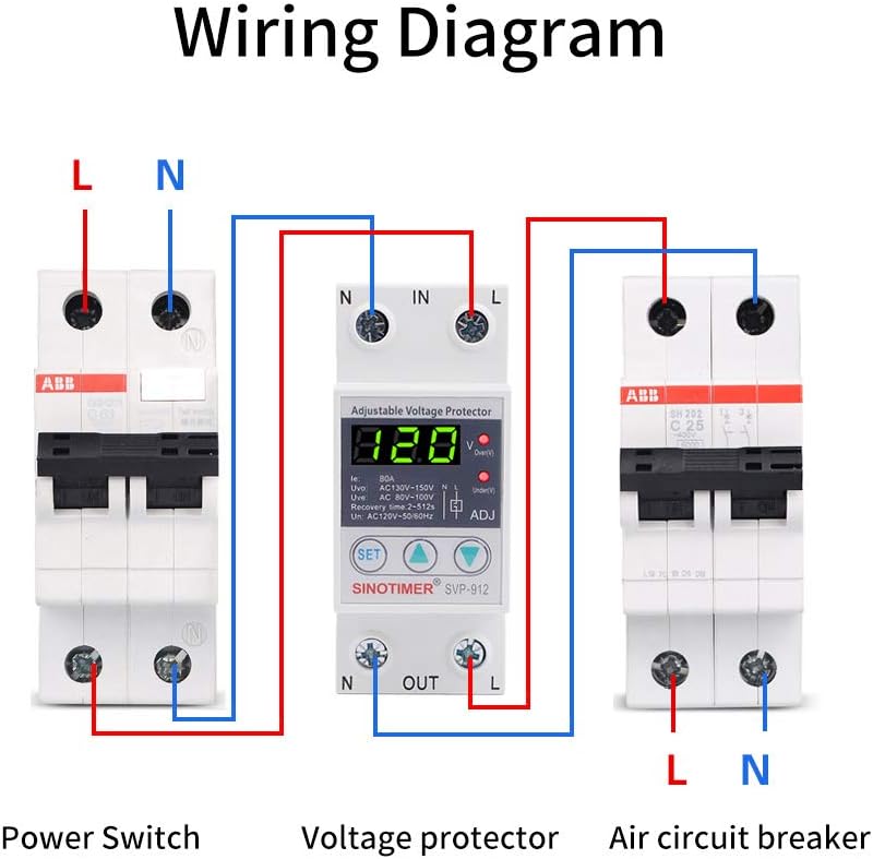
Figure 3: Wiring diagram illustrating the connection of the SVP912 between a power switch and an air circuit breaker, showing input (IN) and output (OUT) terminals for Line (L) and Neutral (N).
After wiring, double-check all connections for tightness and correctness before restoring power.
5. Operation
Upon power-up, the SVP912 will display the current voltage and current readings. The device is pre-configured with default protection values, which can be adjusted as needed.
5.1 Display and Indicators
- The main LED display shows the real-time voltage (V) and current (A).
- The 'Over(V)' LED illuminates when an overvoltage condition is detected.
- The 'Under(V)' LED illuminates when an undervoltage condition is detected.

Figure 4: Close-up view of the SVP912's control panel, highlighting the 'SET' button, adjustment arrows, and LED indicators for Over(V) and Under(V).
5.2 Adjusting Protection Parameters
To adjust the protection values:
- Press the SET button to enter the parameter setting mode. The display will show the first adjustable parameter (e.g., overvoltage threshold).
- Use the Up (▲) and Down (▼) arrow buttons to increase or decrease the value.
- Press SET again to confirm the current parameter and move to the next adjustable parameter (e.g., undervoltage threshold, overcurrent limit, recovery delay time).
- Repeat steps 2 and 3 for all desired parameters.
- After setting the last parameter, the device will automatically save the settings and return to normal operation mode.
Refer to the labels on the device (e.g., Uvo: AC130V-150V, Uve: AC80V-100V, Recovery time: 2-512s) for the default ranges and units of adjustable parameters.
6. Maintenance
The SINOTIMER SVP912 is designed for reliable, long-term operation with minimal maintenance. Periodically inspect the device and its connections for any signs of wear, damage, or loose wiring. Ensure the area around the protector is clean and free from dust or debris to maintain proper ventilation.
7. Troubleshooting
If the device is not functioning as expected, consider the following:
- No Display/No Power: Check the incoming power supply and ensure all wiring connections are secure. Verify the upstream circuit breaker is not tripped.
- Frequent Tripping: Review your set overvoltage, undervoltage, and overcurrent thresholds. They might be set too sensitively for your application. Check for actual voltage fluctuations or excessive current draw from connected appliances.
- Device Not Recovering: Ensure the fault condition (over/undervoltage, overcurrent) has genuinely cleared and remained stable for the set recovery delay time.
- Incorrect Readings: If the displayed voltage or current seems inaccurate, ensure proper wiring and contact a qualified electrician for verification.
For persistent issues, consult a qualified electrician or contact SINOTIMER customer support.
8. Warranty and Support
The SINOTIMER SVP912 comes with a 1-Year Manufacturer Warranty. This warranty covers defects in materials and workmanship under normal use. Please retain your proof of purchase for warranty claims.
For technical support, warranty service, or further inquiries, please contact SINOTIMER directly through their official channels or visit their brand store for more information.
You can find more information about SINOTIMER products and support at the SINOTIMER Store.