1. Product Overview
The VEVOR 3/4" NPT 4-Stage Air Compressor Filter Regulator is designed to deliver clean, dry, and regulated compressed air for various applications. This system integrates multi-stage filtration, desiccant drying, and stable pressure regulation to protect air tools and ensure efficient operation.
Key Features:
- 4-Stage Filtration and Drying: Includes a 5µm brass filter, 0.3µm sponge filter, and two 0.1µm desiccant dryer stages for comprehensive impurity and moisture removal.
- Stable Pressure Regulation: Features an adjustable pressure regulating knob to maintain consistent output pressure up to 175 PSI.
- Automatic Drainage: Equipped with a built-in float switch for hands-free, automatic condensate drainage, reducing maintenance and preventing equipment damage.
- Durable Construction: Constructed with an aluminum alloy body for resistance to pressure, corrosion, and impact, suitable for industrial and home use.
- Standard 3/4" NPT Ports: Compatible with most standard air compressor systems.

Figure 1: Overview of the 4-stage filtration and pressure regulation system. Air enters from the inlet, passes through the 5µm brass filter, 0.3µm sponge filter, and two 0.1µm desiccant dryers before exiting the outlet. The pressure regulating knob is visible at the top.
2. Safety Instructions
Read and understand all instructions before installing or operating this product. Failure to follow these instructions may result in property damage, personal injury, or death.
- Always wear appropriate personal protective equipment (PPE), including eye protection, when working with compressed air systems.
- Ensure the air compressor is turned off and depressurized before installation, maintenance, or any adjustments.
- Do not exceed the maximum working pressure of 175 PSI (12 Bar).
- Verify that all connections are secure and leak-free before operating the system.
- Ensure the airflow direction indicated by the arrow on the product aligns with the system's airflow.
- Keep children and unauthorized personnel away from the compressed air system.
- Do not modify the product in any way. Use only original replacement parts.
- Operate the unit within the specified temperature range of 41-140 °F (5-60 °C).
3. Product Components
The VEVOR Air Compressor Filter Regulator consists of the following main components:
- Pressure Regulating Knob: Used to adjust and lock the output air pressure.
- Pressure Gauge: Displays the regulated output air pressure.
- 5µm Brass Filter Element: First stage of filtration, removes larger impurities.
- 0.3µm Sponge Filter Element: Second stage of filtration, removes smaller particulate impurities.
- 0.1µm Desiccant Dryer (x2): Third and fourth stages, remove moisture from the air.
- Automatic Drain Valve: Releases accumulated condensate automatically.
- Inlet and Outlet Ports: 3/4" NPT threaded connections for air input and output.
- Mounting Brackets: For secure installation.

Figure 2: Detailed view of the filtration and drying stages, along with instructions for adjusting the pressure regulating knob (pull out to unlock, rotate to adjust, press down to lock).
4. Installation and Setup
Proper installation is crucial for the performance and longevity of the filter regulator. Follow these steps carefully:
- Prepare the Installation Area: Choose a location that is easily accessible for maintenance and away from direct heat or moisture. Ensure sufficient space around the unit.
- Clean Ports and Fittings: Before connecting, thoroughly clean all ports and fittings to prevent dust or debris from entering the air system.
- Apply Thread Sealant: Wrap PTFE tape (thread seal tape) around the threads of all fittings to ensure an airtight seal and prevent air leakage.
- Connect Inlet and Outlet: Identify the inlet and outlet ports on the filter regulator. The airflow direction is indicated by an arrow on the unit. Connect the air supply line to the inlet and the air tool/system line to the outlet. Ensure the connections are tight.
- Mount the Unit: Securely mount the filter regulator using the integrated mounting brackets.
- Initial Pressure Check: Slowly introduce air pressure into the system. During the first installation, slight leakage may occur due to the difference between internal and initial external pressure. Allow the excess air to expel; the leakage should stop. Check all connections for leaks using a soapy water solution.

Figure 3: Illustration of the 3/4" NPT port size and how the filter regulator connects to an air compressor system.

Figure 4: Clear markings for inlet and outlet ports, emphasizing the importance of correct airflow direction and proper sealing during installation.
5. Operating Instructions
Once installed, the VEVOR Air Compressor Filter Regulator is designed for straightforward operation.
- Power On Air Compressor: Turn on your air compressor and allow it to build up to its operating pressure.
- Adjust Output Pressure:
- Pull the pressure regulating knob upwards to unlock it.
- Rotate the knob clockwise to increase pressure or counter-clockwise to decrease pressure. Observe the pressure gauge for the desired setting.
- Once the desired pressure is set, press the knob downwards to lock it in place.
- Monitor Filtration: The transparent bowls allow visual inspection of the filter elements and desiccant beads.
- Automatic Drainage: The integrated float switch will automatically drain accumulated water from the filter bowls when the water level reaches a certain point. No manual intervention is typically required for drainage.
6. Maintenance
Regular maintenance ensures optimal performance and extends the lifespan of your filter regulator.
Filter Element Maintenance:
The filter elements are reusable and can be cleaned or replaced as needed.
- Depressurize System: Turn off the air compressor and completely depressurize the air system before performing any maintenance.
- Detach Housing: Rotate the filter bowl housing to detach it from the main unit.
- Remove Filter: Carefully detach the filter element (brass or sponge) from its housing, often with the aid of a screwdriver.
- Clean or Replace:
- Brass Filter Element: Clean by rinsing with water or blowing with compressed air from the inside out.
- Sponge Filter Element: Clean by rinsing with water. If heavily soiled or damaged, replace with a new one.
- Desiccant Dryers: Monitor the color of the desiccant beads. When they change color (indicating saturation), they need to be replaced.
- Reinstall: Reinstall the cleaned or new filter element and reattach the housing securely. Ensure O-rings are properly seated to prevent leaks.

Figure 5: The brass filter element, designed for reusability and extended lifespan.

Figure 6: Step-by-step guide for maintaining the reusable filter elements: 1. Rotate to detach housing, 2. Detach filter with screwdriver, 3. Replace or clean filter, 4. Reinstall filter in place.
Automatic Drain System:
The automatic drain system requires minimal maintenance. Periodically check the drain outlet to ensure it is not clogged. If the drain is not functioning correctly, ensure the float switch mechanism is free of debris.

Figure 7: The automatic drain system, showing condensate being expelled from the bottom of the filter bowl.
7. Troubleshooting
This section addresses common issues you might encounter with the VEVOR Air Compressor Filter Regulator.
| Problem | Possible Cause | Solution |
|---|---|---|
| Air leakage at connections | Improperly sealed threads; loose fittings; damaged O-rings. | Ensure PTFE tape is properly applied. Tighten all fittings. Inspect and replace damaged O-rings. For initial installation, allow minor leakage to cease as pressure stabilizes. |
| Poor air quality (moisture/particles still present) | Clogged filter elements; saturated desiccant beads; incorrect airflow direction. | Inspect and clean/replace filter elements (brass, sponge). Replace desiccant beads if saturated (color change). Verify airflow direction matches the arrow on the unit. |
| Pressure gauge shows no reading or incorrect pressure | Gauge malfunction; no air supply; pressure regulating knob not adjusted or locked. | Check air supply to the unit. Ensure the pressure regulating knob is pulled up to adjust and then pressed down to lock. If issues persist, the gauge may need replacement. |
| Automatic drain not functioning | Drain outlet clogged; float switch mechanism obstructed. | Check and clear any obstructions from the drain outlet. Inspect the float switch inside the bowl for debris and ensure it moves freely. |
| Inconsistent output pressure | Pressure regulating knob not locked; fluctuating input pressure; internal regulator issue. | Ensure the pressure regulating knob is pressed down to lock. Verify stable input pressure from the compressor. If the problem persists, the regulator may require professional inspection. |
8. Technical Specifications
| Specification | Value |
|---|---|
| Model Number | AWF+AM+AMK+AMK40-06D |
| Port Size | 3/4" NPT |
| Air Flow | 140 SCFM |
| Max Working Pressure | 175 PSI (12 Bar) |
| Operating Temperature Range | 41-140 °F (5-60 °C) |
| Drain Type | Auto Drainage |
| Housing Material | Aluminum Alloy |
| Filter Material | 5µm Brass Filter Element + 0.3µm Sponge Filter + 0.1µm Desiccant Dryer + 0.1µm Desiccant Dryer |
| Product Dimensions (L x W x H) | 32.51 x 11 x 30 cm (12.8 x 4.33 x 11.81 inches) |
| Net Weight | 4.16 kg (9.17 lbs) |
| Included Components | 1 x Air Compressor Filter Regulator |
| Manufacturer | VEVOR |
| Country of Origin | China |
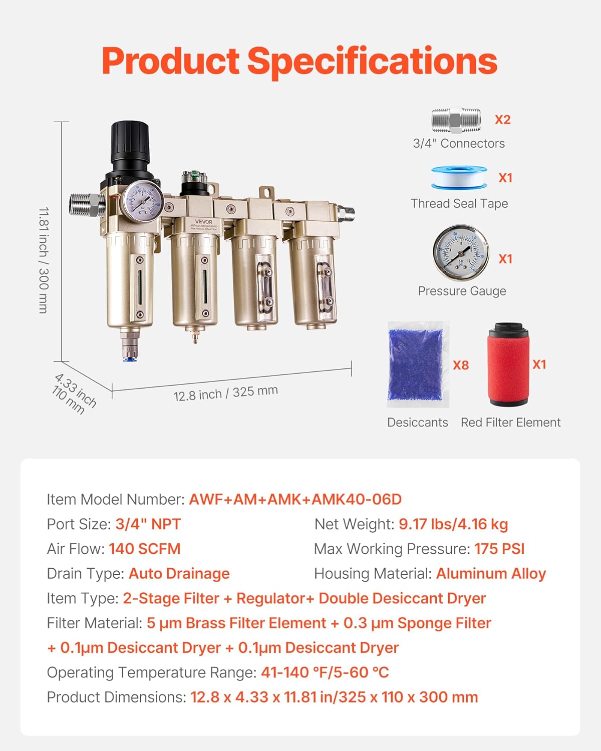
Figure 8: Visual representation of the product's dimensions and a list of included accessories.
9. Warranty and Support
Specific warranty details and direct support contact information are not provided within this manual. For warranty claims, technical assistance, or to inquire about replacement parts, please refer to the VEVOR official website or contact your point of purchase. Keep your purchase receipt as proof of purchase.