Introduction
This manual provides detailed instructions for the safe and effective operation of your Jauarta VC837 NCV Digital Automatic Multimeter. Please read this manual thoroughly before use and retain it for future reference.
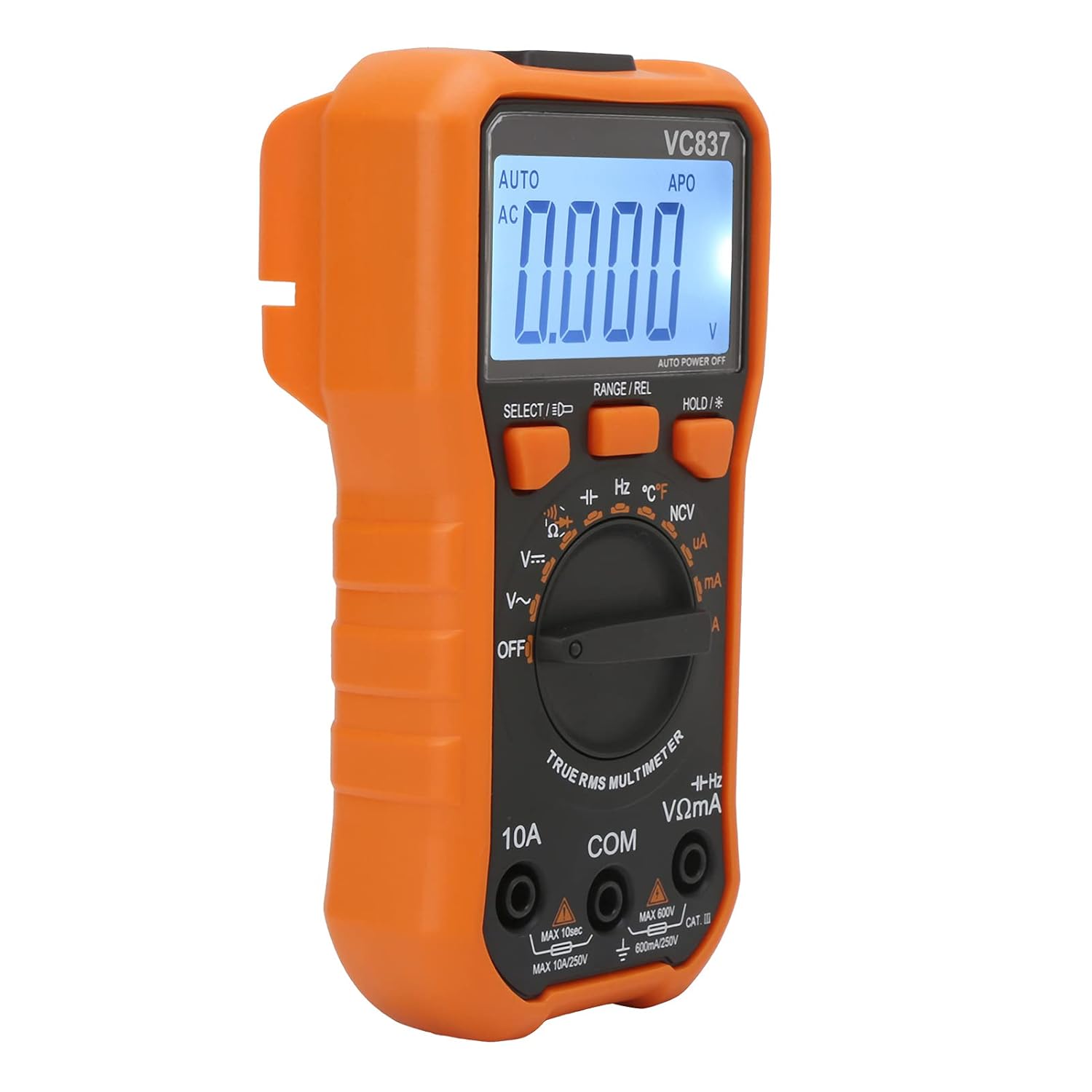
The Jauarta VC837 is a versatile digital multimeter designed for measuring various electrical parameters, including AC/DC voltage, AC/DC current, resistance, capacitance, frequency, and temperature. It features a 6000-count display, automatic ranging, non-contact AC voltage (NCV) detection, and a backlight function for improved visibility.
Safety Information
WARNING: To avoid electric shock or personal injury, read and understand all safety information before using this product.
- Always ensure the multimeter is in good working condition before use. Inspect test leads for damage.
- Do not apply more than the rated voltage, as marked on the multimeter, between the terminals or between any terminal and earth ground.
- Use caution when working with voltages above 30V AC RMS, 42V peak, or 60V DC. These voltages pose a shock hazard.
- Always disconnect the test leads from the circuit before changing functions or ranges.
- Do not operate the multimeter with the case open or if the battery cover is not securely closed.
- Replace the battery as soon as the low battery indicator appears to ensure accurate readings.
- Adhere to local and national safety codes.
Product Features
- 6000 Counts Display: Provides precise measurement readings.
- Automatic Ranging: Simplifies operation by automatically selecting the correct measurement range.
- Non-Contact AC Voltage (NCV) Sensing: Detects AC voltage without direct contact, enhancing safety.
- True RMS Measurement: Ensures accurate readings for non-sinusoidal waveforms.
- Backlight Function: Improves visibility in dimly lit environments.
- Diode Test: Checks the functionality of diodes.
- Data Hold: Freezes the displayed reading for convenient recording.
- Continuity Alarm: Audible alert for circuit continuity (less than 50Ω).
- Automatic Shutdown: Conserves battery life by powering off after approximately 15 minutes of inactivity.
- Low Voltage Display: Indicates when battery power is low (below 2.4V).
- Function Protection/Shock Protection: Designed for durability and user safety.
Setup
1. Battery Installation
The Jauarta VC837 Multimeter requires 2 x AAA 3V batteries (not included).
- Locate the battery compartment on the back of the multimeter.
- Use a screwdriver to open the battery compartment cover.
- Insert two AAA batteries, observing the correct polarity (+ and -) as indicated inside the compartment.
- Securely close the battery compartment cover.
2. Initial Inspection
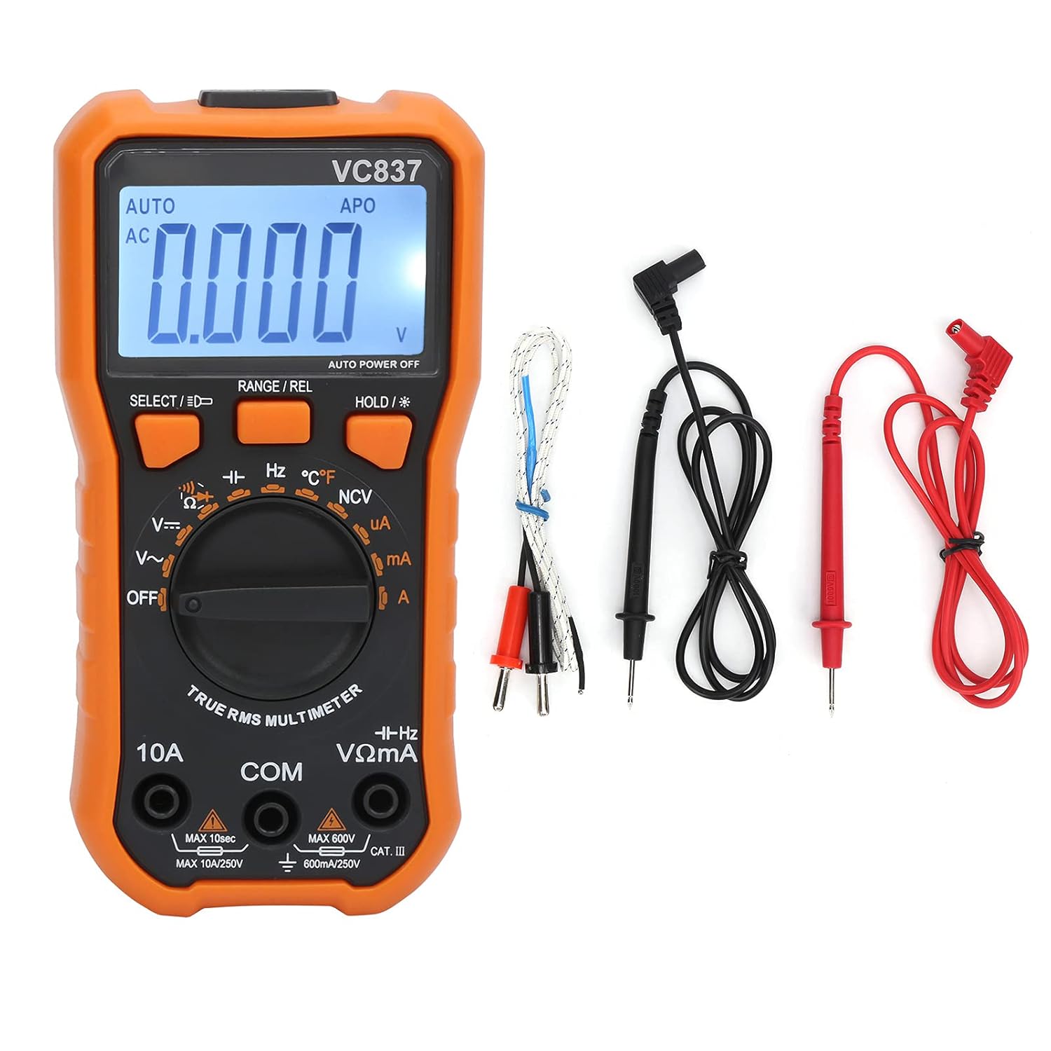
Before first use, inspect the multimeter and its accessories for any signs of damage. Ensure the test leads are intact and free from cracks or exposed wiring.
Operating Instructions
The VC837 multimeter offers both manual and automatic ranging modes. For most measurements, the automatic range simplifies operation.
General Operating Principles
- Initial State: When no measurement is being taken and the leads are not connected to a circuit, the display should typically show "0.000" or similar.
- Horizontal Placement: For optimal stability and display viewing, place the multimeter horizontally on a stable surface.
- Changing Functions: Always disconnect the test leads from the circuit before rotating the function switch to a new measurement mode. This prevents potential damage to the multimeter or the circuit.
- High Voltage/Current: Exercise extreme caution when measuring high voltages or currents. Ensure the correct range is selected to avoid damaging the multimeter or causing injury.
Measurement Functions
1. DC Voltage Measurement (V=)
Range: 600mV / 6V / 60V / 600V
- Insert the red test lead into the "VΩmA" jack and the black test lead into the "COM" jack.
- Turn the rotary switch to the "V=" position.
- Connect the test leads across the DC voltage source or component to be measured.
- Read the voltage value on the display.
2. AC Voltage Measurement (V~)
Range: 6V / 60V / 600V
- Insert the red test lead into the "VΩmA" jack and the black test lead into the "COM" jack.
- Turn the rotary switch to the "V~" position.
- Connect the test leads across the AC voltage source or component to be measured.
- Read the voltage value on the display.
3. DC Current Measurement (uA/mA/A)
Range: 600uA / 6000uA / 60mA / 600mA / 6A / 10A
- For uA/mA: Insert the red test lead into the "VΩmA" jack and the black test lead into the "COM" jack.
- For A: Insert the red test lead into the "10A" jack and the black test lead into the "COM" jack.
- Turn the rotary switch to the appropriate "uA", "mA", or "A" position.
- Disconnect power to the circuit. Open the circuit where current is to be measured.
- Connect the multimeter in series with the circuit.
- Apply power to the circuit and read the current value.
4. AC Current Measurement (uA/mA/A)
Range: 600uA / 6000uA / 60mA / 600mA / 6A / 10A
- Follow the same connection steps as for DC Current, ensuring the red lead is in the correct jack (VΩmA for uA/mA, 10A for A).
- Turn the rotary switch to the appropriate "uA~", "mA~", or "A~" position.
- Connect the multimeter in series with the circuit.
- Apply power to the circuit and read the current value.
5. Resistance Measurement (Ω)
Range: 600Ω / 6kΩ / 60kΩ / 600kΩ / 6MΩ / 60MΩ
- Insert the red test lead into the "VΩmA" jack and the black test lead into the "COM" jack.
- Turn the rotary switch to the "Ω" position.
- Ensure the circuit or component is de-energized before measuring resistance.
- Connect the test leads across the component to be measured.
- Read the resistance value on the display.
6. Capacitance Measurement (F)
Range: 60nF / 600nF / 6uF / 60uF / 600uF / 6mF / 60mF
- Insert the red test lead into the "VΩmA" jack and the black test lead into the "COM" jack.
- Turn the rotary switch to the "F" position.
- Ensure the capacitor is fully discharged before measurement to prevent damage to the multimeter.
- Connect the test leads across the capacitor.
- Read the capacitance value on the display.
7. Frequency Measurement (Hz)
Range: 10Hz / 100Hz / 1kHz / 10kHz / 100kHz / 1MHz / 10MHz
- Insert the red test lead into the "VΩmA" jack and the black test lead into the "COM" jack.
- Turn the rotary switch to the "Hz" position.
- Connect the test leads across the signal source.
- Read the frequency value on the display.
8. Temperature Measurement (°C/°F)
Range: -40℃~1000℃ / 0℉~1832℉
- Insert the temperature probe into the "VΩmA" and "COM" jacks, observing polarity if applicable.
- Turn the rotary switch to the "℃/℉" position.
- Place the tip of the temperature probe on or near the object whose temperature is to be measured.
- Read the temperature value on the display. Use the "SELECT" button to switch between Celsius and Fahrenheit.
9. Diode Test
- Insert the red test lead into the "VΩmA" jack and the black test lead into the "COM" jack.
- Turn the rotary switch to the diode symbol position.
- Connect the red lead to the anode and the black lead to the cathode of the diode.
- A forward voltage drop will be displayed for a good diode. Reverse the leads; the display should show "OL" (Open Loop).
10. Continuity Test
- Insert the red test lead into the "VΩmA" jack and the black test lead into the "COM" jack.
- Turn the rotary switch to the continuity symbol position.
- Connect the test leads across the circuit or component.
- If the resistance is less than approximately 50Ω, the buzzer will sound, indicating continuity.
11. Non-Contact AC Voltage (NCV) Detection
- Turn the rotary switch to the "NCV" position.
- Move the top end of the multimeter near an AC voltage source (e.g., a live wire or outlet).
- The multimeter will emit an audible beep and the NCV indicator will light up, indicating the presence of AC voltage.
Button Functions
- SELECT / ★: Used to switch between different measurement modes within a single rotary switch position (e.g., AC/DC for voltage/current, Celsius/Fahrenheit for temperature). A long press activates the backlight.
- RANGE / REL: Toggles between automatic and manual ranging. A long press activates the Relative Measurement function.
- HOLD / ★: Freezes the current reading on the display. A long press activates/deactivates the backlight.
Maintenance
1. Cleaning
Wipe the case with a damp cloth and mild detergent. Do not use abrasives or solvents. Ensure the multimeter is completely dry before use.
2. Battery Replacement
When the low battery indicator appears on the display, replace the batteries immediately to ensure accurate measurements and proper operation. Refer to the "Battery Installation" section under Setup.
3. Fuse Replacement (if applicable)
If the current measurement function fails, the fuse may need replacement. This procedure should only be performed by qualified personnel. Ensure the multimeter is disconnected from all circuits and power sources before attempting fuse replacement. Use only fuses of the specified type and rating.
4. Storage
If the multimeter is not used for an extended period, remove the batteries to prevent leakage and damage. Store the device in a cool, dry place, away from direct sunlight and extreme temperatures.
Troubleshooting
| Problem | Possible Cause | Solution |
|---|---|---|
| No display or dim display | Dead or low batteries; incorrect battery installation. | Replace batteries; check battery polarity. |
| "OL" (Overload) displayed | Measurement exceeds selected range; open circuit (for continuity/resistance). | Select a higher range (if in manual mode); check circuit connections. |
| Inaccurate readings | Low battery; incorrect function/range selected; damaged test leads. | Replace batteries; verify function/range; inspect and replace test leads if damaged. |
| Current measurement not working | Blown fuse; incorrect test lead connection. | Check and replace fuse (if qualified); ensure leads are in the correct current jacks (mA/A). |
| NCV not detecting AC voltage | Distance too far; weak AC field. | Bring the NCV sensor closer to the AC source. |
Specifications
| Parameter | Range / Value | Basic Accuracy |
|---|---|---|
| DC Voltage | 600mV/6V/60V/600V | ±(0.5%+4) |
| AC Voltage | 6V/60V/600V | ±(0.8%+6) |
| DC Current | 600uA/6000uA/60mA/600mA/6A/10A | ±(1.0%+5) |
| AC Current | 600uA/6000uA/60mA/600mA/6A/10A | ±(1.5%+5) |
| Resistance | 600Ω/6kΩ/60kΩ/600kΩ/6MΩ/60MΩ | ±(0.8%+1) |
| Capacitance | 60nF/600nF/6uF/60uF/600uF/6mF/60mF | ±(2.5%+8) |
| Frequency | 10Hz/100Hz/1kHz/10kHz/100kHz/1MHz/10MHz | ±(0.5%+4) |
| Temperature | -40℃~1000℃ / 0℉~1832℉ | ±(1.0%+5) |
| Power Supply | 2 x AAA 3V batteries (not included) | N/A |
| Maximum Display | 6000 counts | N/A |
| Automatic Shutdown | Approx. 15 minutes | N/A |
| Input Impedance | 10MΩ | N/A |
| Sampling Rate | 3 times/sec | N/A |
| AC Frequency Response | 40Hz-2kHz | N/A |
Product Images


Warranty and Support
Specific warranty details are not provided in the product description. For warranty information and technical support, please contact Jauarta customer service directly or refer to the product packaging.
For further assistance, please visit the official Jauarta website or contact their support channels.