Introduction
This instruction manual provides detailed guidance for assembling and operating the PEMENOL DIY Solder Kit Power Supply Module. This kit is designed for individuals interested in practicing soldering techniques and gaining knowledge about electronic components and voltage conversion. Upon completion, you will have a functional power supply module with adjustable output voltage for various electronic experiments and tests.
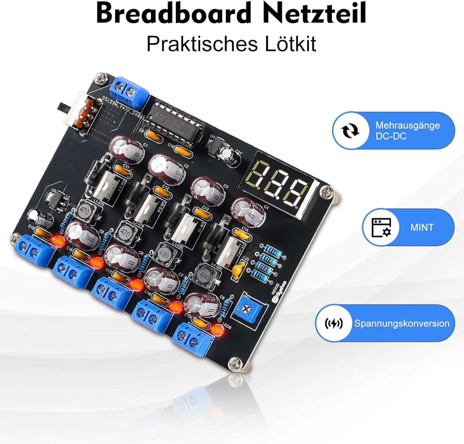
Image 1: The PEMENOL DIY Solder Kit Power Supply Module, showcasing its components and design. This image highlights the practical nature of the solder kit.
Safety Information
Please read and understand all safety instructions before beginning assembly or operation. Failure to follow these instructions may result in injury or damage to the product.
- Always work in a well-ventilated area when soldering.
- Wear appropriate personal protective equipment, including safety glasses, to protect against solder splashes and fumes.
- Use a soldering iron with proper temperature control and ensure it is placed in a safe holder when not in use.
- Avoid touching hot components or the tip of the soldering iron.
- Ensure the power supply is disconnected before making any adjustments or modifications to the circuit.
- Keep the module away from moisture and extreme temperatures.
- This kit contains small parts and is not suitable for children without adult supervision.
Package Contents
Verify that all components listed below are present in your kit before starting assembly:
- Printed Circuit Board (PCB)
- Various electronic components (resistors, capacitors, diodes, ICs, potentiometers, LED, etc.)
- Digital LED display module
- Input/Output terminals
- Detailed instruction manual (this document serves as a guide)
This kit contains a variety of electronic components and a detailed guide to assist you step-by-step through the soldering process.
Setup and Assembly
This is a DIY solder kit that requires assembly. Follow the instructions carefully to ensure proper functionality. The kit is designed for beginners and enthusiasts interested in electronics.
- Component Identification: Before soldering, identify all components using the provided component list and the markings on the PCB.
- Soldering Order: It is generally recommended to solder smaller components (resistors, diodes) first, followed by larger components (capacitors, IC sockets, terminals). This prevents larger components from obstructing access to smaller pads.
- Polarity: Pay close attention to the polarity of components such as diodes, electrolytic capacitors, and integrated circuits (ICs). Incorrect polarity can damage the components or the entire module.
- Solder Joints: Ensure each solder joint is shiny, smooth, and forms a good connection without bridging to adjacent pads.
- Digital Display: Carefully solder the digital LED display module to its designated position.
- Input/Output Terminals: Solder the input and output terminals securely.

Image 2: Wiring Diagram. This diagram illustrates the input voltage connection (DC 15V-20V) and the various output terminals including 1.5V, 3.3V, 5.0V, 12V, and an adjustable output from 2.2V to Vin. The 1.5V socket provides a maximum current of 1A, while all other sockets can output a maximum current of 4A.
Operating Instructions
Once assembled, the power supply module is ready for operation. It features an adjustable output voltage and a digital display.
- Power Input: Connect a DC power source (15V-20V) to the input terminals (Vin and GND). The maximum input power is 36W.
- LED Indicator: A red LED indicator light will illuminate when the board is powered, confirming the module is receiving power.
- Output Voltages: The module provides fixed output voltages of 1.5V, 3.3V, 5V, and 12V.
- Adjustable Output: The integrated potentiometer allows you to adjust the output voltage on the ADJ terminal. Use a "+" screwdriver to turn the potentiometer and change the output voltage. The adjustable range is typically 2.2V to Vin (input voltage).
- Digital Display: The three-digit LED digital display shows the current output voltage, allowing for precise adjustment.
- Current Output: The 1.5V output socket provides a maximum current of 1A. All other output sockets (3.3V, 5V, 12V, and ADJ) can output a maximum current of 4A.

Image 3: Product Details. This image highlights key features such as the regulated output current, LED indicator, power switch, and output voltage display. Dimensions are approximately 10cm x 7cm x 3cm.
Maintenance
The PEMENOL Power Supply Module is designed for durability. Regular maintenance is minimal but important for longevity.
- Cleaning: Keep the module clean and free from dust and debris. Use a soft, dry cloth for cleaning. Avoid using liquids or solvents.
- Storage: Store the module in a dry, cool environment when not in use.
- Inspection: Periodically inspect solder joints and components for any signs of damage or loose connections. Re-solder if necessary.
Troubleshooting
Refer to the following points if you encounter issues with your power supply module:
- Output Voltage Lower Than Input: The module functions as a voltage reducer. The output voltage will always be lower than the input voltage, with a minimum voltage difference of 0.3V.
- Voltage Difference: The lower the input voltage, the greater the voltage difference between input and output, typically ranging from 0.1V to 0.3V.
- Dim/Off Display: If the input voltage drops below 4V, the brightness of the digital display will significantly decrease. It will turn off completely at 3.8V. Ensure adequate input voltage.
- ADJ Output Voltage Limits:
- If input voltage drops below 6.5V, the highest ADJ output voltage reaches 6.5V.
- If input voltage drops below 6.5V, the lowest ADJ output voltage is above 2.2V.
- If the input voltage is 15V, the ADJ output voltage range is 2.2V to 14.8V.
- If the input voltage exceeds 15.2V, the maximum ADJ output voltage is 15.2V.
- Dim Red Indicator Light: If the output voltage is below the normal expected value, the brightness of the red indicator light will be dim. Check connections and input voltage.
- Maximum Input Voltage: To prevent damage, the maximum recommended test input voltage is 20V. Do not exceed this limit.

Image 4: Detailed information regarding voltage reduction function, display brightness behavior at low input voltages, and ADJ output voltage limits under various input conditions. This is crucial for understanding the module's operational characteristics and troubleshooting.
Specifications
| Feature | Specification |
|---|---|
| Brand | PEMENOL |
| Model Name | PEMENOL |
| Recommended Uses | Office, Electronic Experiments |
| Power Source | External Power Source |
| Input Power (Max) | 36 Watts |
| Output Power | 100 Watts (Peak), 36 Watts (Continuous) |
| Output Voltage | 1.5V, 3.3V, 5V, 12V (Fixed); 2.2V to Vin (Adjustable) |
| Output Current | 1A (1.5V output), 4A (Other outputs) |
| Item Weight | 80 Grams |
| Certifications | CE Compliant |
| Output Waveform | Modified Sine Wave |

Image 5: Application Scenarios. This image illustrates various uses for the power supply module, including education and training, electronics development, testing, and DIY soldering projects.
Warranty Information
This product comes with a standard manufacturer's warranty. Please refer to the packaging or contact the seller for specific warranty terms and conditions. Keep your proof of purchase for any warranty claims.
Customer Support
For technical assistance, troubleshooting, or inquiries regarding your PEMENOL DIY Solder Kit Power Supply Module, please contact PEMENOL customer support through the retailer's platform or visit the official PEMENOL website for contact information.


