1. Introduction
This manual provides essential information for the safe and effective use of the VEVOR AT1-2200X Variable Frequency Drive (VFD). The VFD is designed to convert single-phase AC 220-240V input into three-phase AC 220V-240V output, enabling precise speed control for compatible AC motors. It features a 2.2KW (3HP) power rating and a 10A current capacity, with an output frequency range of 0-400Hz.
Key Features:
- Unparalleled Quality: Provides soft start and stop functions, steady motor control, and energy efficiency.
- Effortless Setup & Operation: Features an intuitive control panel, clear display, and a frequency adjustment knob for streamlined operations. A detachable panel with a 7.9-inch cable allows for convenient remote use.
- Safety & Durability Redefined: Incorporates a 10-layer protection system against overcurrent, overload, overvoltage, and phase loss. The circuit board is treated with triple-proof paint for enhanced longevity.
- Efficient Heat Dissipation: Equipped with a powerful cooling fan and a multi-sided, multi-hole design to ensure optimal ventilation and low noise operation during extended use.
- Master of Versatility: Suitable for driving 3-phase motors in various machinery, including compressors, lathes, fans, and milling machines.
2. Safety Precautions
Adherence to the following safety guidelines is crucial to prevent injury, property damage, and ensure the proper functioning of the VFD:
- Always disconnect power before performing any wiring or maintenance. Failure to do so may result in severe injury or death.
- Never connect the U/V/W output terminals directly to an AC power supply. This will cause irreparable damage to the inverter.
- Do not install the inverter on flammable surfaces or near flammable materials to avoid fire hazards.
- Ensure the ground terminal of the inverter is properly and securely grounded.
- Avoid installing the VFD in environments with explosive gases to prevent the risk of explosion.
- Only qualified professionals should perform wiring and internal maintenance. The converter contains high voltage, and unauthorized opening of the shell is prohibited.

Figure 2.1: Front view of the VEVOR AT1-2200X VFD, showing the control panel and integrated safety warning label.
3. Product Overview
The VEVOR AT1-2200X VFD is designed for efficient motor speed control. Below are the main components and their functions.
Control Panel Layout:

Figure 3.1: Detailed view of the VFD control panel.
- Status Indicator: Displays operational status (Power, Run, Stop, FWD, REV, r/min).
- 5-Digit LED Display Screen: Shows frequency, parameters, and error codes.
- FWD/REV Key: Toggles forward and reverse motor rotation.
- DISP Key: Shifts between display modes or acts as a jog in normal mode.
- PROG Key: Enters or exits programming mode.
- FUNC/DATA Key: Selects programming modes or confirms data settings.
- Up/Down Keys (▲ / ▼): Navigates through parameters or adjusts values.
- Speed Adjustment Knob: Manually adjusts the output frequency/motor speed.
- RUN Key: Starts the inverter output.
- STOP/RESET Key: Stops the inverter output or resets fault conditions.
Internal Components and Protection:
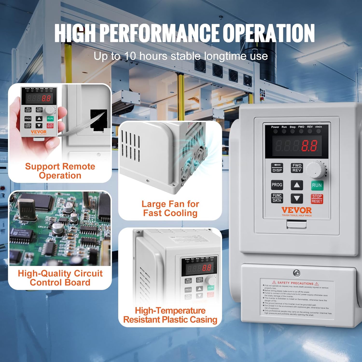
Figure 3.2: Internal view highlighting the cooling fan and circuit board.
The VFD features a robust design for reliable performance:
- High-Quality Circuit Control Board: Ensures stable and precise operation.
- Large Cooling Fan: Provides efficient heat dissipation to maintain optimal operating temperatures.
- High-Temperature Resistant Plastic Casing: Offers durability and protection for internal components.

Figure 3.3: Overview of the VFD's comprehensive protection system.
The VFD incorporates a 10-level multiple protection system, including:
- Overcurrent Protection
- Overvoltage Protection
- Overheat Protection
- Reverse Power Protection
- Ground Short Circuit Protection
- Input Phase-Loss Protection
- Output Phase-Loss Protection
- Load Overload 100% Protection
- Load Overload 150% Protection
- Inverter Overload 150% Protection
4. Setup and Installation
Wiring Instructions:
Proper wiring is essential for safe and correct operation. Refer to the diagram below for connecting the VFD.

Figure 4.1: Wiring diagram for the VEVOR AT1-2200X VFD.
| Terminal Label | Function Description |
|---|---|
| L, N | Single phase AC 220V input terminal |
| U, V, W | Output terminal connect to three phase motor |
| GND | Grounding terminal |
Important Considerations:
- Ensure all connections are secure and properly insulated.
- Verify that the input voltage matches the VFD's specifications (AC 220-240V single phase).
- The VFD does not support external braking resistors.
- For heavier motor loads, it is recommended to select a VFD with a higher power rating than the motor for optimal performance.
Mounting:
The VFD is designed for wall mounting. Ensure the mounting surface is stable and capable of supporting the unit's weight. Allow adequate clearance around the VFD for ventilation and heat dissipation.
5. Operation
Basic Controls:
- Starting the Motor: Press the RUN button to start the motor.
- Stopping the Motor: Press the STOP/RESET button to stop the motor.
- Adjusting Speed: Rotate the Speed Adjustment Knob to increase or decrease the motor's operating frequency.
- Changing Direction: Use the FWD/REV key to switch between forward and reverse rotation.
- Display Information: Press the DISP key to cycle through various display parameters such as output frequency, current, voltage, etc.
Programming Parameters:
The VFD offers extensive programming capabilities to fine-tune its operation for specific applications. To enter programming mode, press the PROG key. Use the Up/Down keys to navigate through parameters and the FUNC/DATA key to select and confirm settings. Refer to the detailed parameter list in the complete user manual for specific adjustments, such as setting the motor's rated frequency (e.g., 60Hz for US motors), acceleration/deceleration times, and other advanced functions.
6. Maintenance
Regular maintenance ensures the longevity and optimal performance of your VFD.
- Cleaning: Periodically clean the exterior of the VFD with a soft, dry cloth. Ensure ventilation openings are free from dust and debris to prevent overheating.
- Ventilation: Confirm that the VFD's cooling fan is operating correctly and that there is unobstructed airflow around the unit.
- Connections: Regularly inspect all wiring connections for tightness and signs of wear or corrosion.
- Environmental Conditions: Ensure the operating environment remains within the specified temperature and humidity ranges.
7. Troubleshooting
If the VFD encounters an issue, the display may show an error code. Consult the full product manual for a comprehensive list of error codes and their corresponding troubleshooting steps. General troubleshooting tips include:
- No Power: Check the input power supply and all power connections.
- Motor Not Running: Verify that the RUN command has been issued and that the motor is properly connected. Check for any active error codes.
- Overload/Overcurrent Errors: Reduce the motor load, check for mechanical issues with the motor or driven equipment, and ensure the VFD is appropriately sized for the application.
- Incorrect Speed: Verify the frequency setting via the speed adjustment knob or programmed parameters. Ensure the motor's rated frequency is correctly set in the VFD's parameters.
- Fault Reset: After resolving a fault, press the STOP/RESET button to clear the error and resume operation.
8. Specifications
The following table details the technical specifications for the VEVOR AT1-2200X Variable Frequency Drive.

Figure 8.1: VFD dimensions and key specifications.
| Specification | Value |
|---|---|
| Item Model Number | AT1-2200X |
| Horsepower | 3HP |
| Power | 2.2KW |
| Current | 10A |
| Input Voltage | AC 220-240V Single Phase |
| Output Voltage | AC 220-240V Three Phase |
| Input Frequency | 50/60Hz |
| Output Frequency | 0-400Hz |
| Operating Temperature | 50°F-104°F / 10°C-40°C |
| Net Weight | 2.6 lbs / 1.2 kg ± 3% |
| Product Dimensions | 3.94 x 5.51 x 5.51 inches |
| Mounting Type | Wall Mount |
9. Warranty and Support
VEVOR products are designed for durability and performance. For information regarding warranty coverage, technical support, or service, please refer to the warranty card included with your product or visit the official VEVOR website. Keep your purchase receipt for warranty claims.


