1. Introduction
Thank you for choosing the Generic TOMZN WiFi Smart ATS Dual Power Automatic Transfer Switch. This device is designed to automatically switch between two power sources (e.g., utility power and generator) to ensure an uninterrupted power supply to your load. Featuring WiFi connectivity, it allows for remote monitoring and control via the EWelink application. Please read this manual thoroughly before installation and operation to ensure safe and efficient use.
2. Safety Information
WARNING: Electrical shock hazard. Installation and maintenance should only be performed by qualified personnel.
- Always disconnect all power sources before installing or servicing the device.
- Ensure all wiring complies with local and national electrical codes.
- Do not operate the switch if it appears damaged.
- This device is designed for indoor use in a dry environment unless properly enclosed for outdoor conditions.
- Verify correct voltage and current ratings before connecting.
3. Product Overview
The TOMZN WiFi Smart ATS is a robust and intelligent solution for managing dual power inputs. It features a durable, flame-retardant, and UV-resistant housing, making it suitable for various environments, including solar installations.
3.1 Key Features
- Automatic switching between two power sources (Source A and Source B).
- WiFi connectivity for remote control and monitoring via EWelink app.
- Manual override function for direct control.
- Protection against short circuits and overloads.
- Insulating materials and screw-type terminals for secure connections.
- Suitable for solar inverters, charge controllers, and battery banks.
3.2 Components
Familiarize yourself with the main components of your ATS device:

Figure 1: Front view of the ATS. This image displays the main body of the automatic transfer switch, highlighting the red manual/auto selector switch, indicators for 'City Power' (Source A) and 'Generator' (Source B), and the various terminal blocks for electrical connections.
- Source A Input Terminals: For connecting the primary power source (e.g., utility grid).
- Source B Input Terminals: For connecting the secondary power source (e.g., generator, solar inverter).
- Load Side Output Terminals: For connecting to the electrical load.
- Manual/Auto Selector Switch: A red rotary switch to select between manual operation (A or B) or automatic mode.
- Manual Buttons (A/B): Used for manual switching when the selector is in the 'Manual' position.
- WiFi Module/Indicator: Integrated module for smart functionality and status indicator.
- Control Terminals (BR BN C NO): For external control or status feedback.
4. Setup and Installation
Proper installation is critical for the safe and reliable operation of your ATS. It is highly recommended that installation be performed by a licensed electrician.
4.1 Mounting
The ATS is designed for DIN rail mounting. Ensure the mounting surface is stable and free from excessive vibration.

Figure 2: Bottom view of the ATS. This image shows the underside of the automatic transfer switch, revealing the integrated blue DIN rail mounting clip and additional screw mounting points for secure attachment within an electrical panel or enclosure.
- Locate a suitable position within your electrical panel or enclosure.
- Attach the ATS to a standard DIN rail by pressing it down until it clicks into place.
- Alternatively, use the screw holes provided on the back for direct mounting if a DIN rail is not available or preferred.
4.2 Wiring Diagram (2P 220V Model)
Refer to the diagram on the device and consult a qualified electrician for correct wiring. The following is a general guide for the 2-pole 220V model:
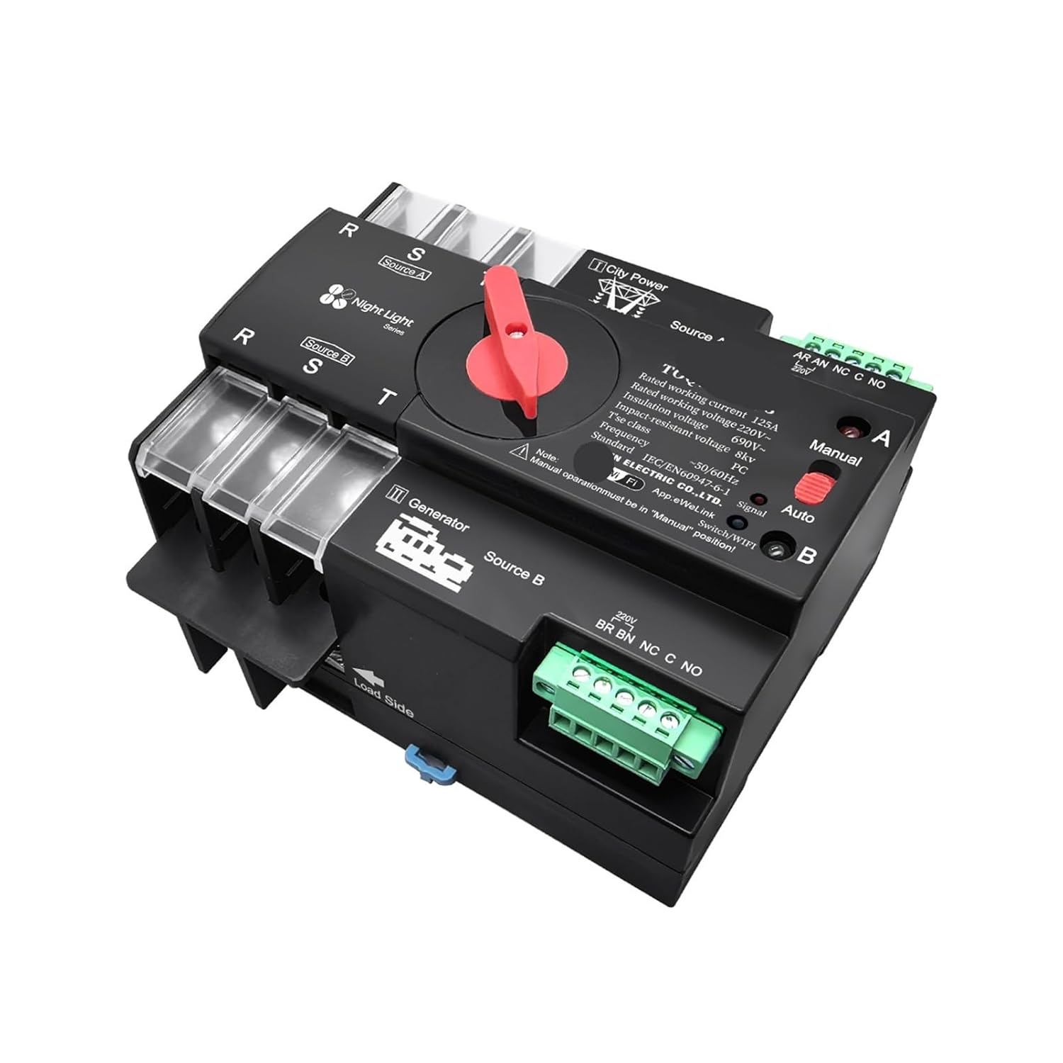
Figure 3: Wiring terminals. This image provides a close-up of the terminal blocks on the ATS, clearly labeling the connections for Source A (City Power), Source B (Generator), and the Load Side, along with smaller terminals for control signals.
- Source A (City Power): Connect your primary power source (e.g., utility grid) to the 'Source A' input terminals. Ensure correct phase and neutral connections.
- Source B (Generator/Secondary Power): Connect your secondary power source (e.g., generator, solar inverter output) to the 'Source B' input terminals.
- Load Side: Connect your electrical load to the 'Load Side' output terminals.
- Control Terminals (BR BN C NO): These terminals are typically used for remote status indication or external control. Consult the specific wiring diagram on the device for their exact function.
- Ensure all screw terminals are tightened securely to prevent loose connections and arcing.
4.3 EWelink App Connection
To utilize the smart features, connect your ATS to the EWelink application:
- Download the EWelink app from your smartphone's app store.
- Register or log in to your EWelink account.
- Ensure your ATS is powered on and in pairing mode (refer to the device's LED indicator for pairing status, usually a rapidly blinking light).
- In the EWelink app, tap '+' to add a device.
- Follow the on-screen instructions to connect the ATS to your home WiFi network.
5. Operating Instructions
5.1 Manual Operation
The ATS can be operated manually using the red selector switch and buttons:
- Rotate the red selector switch to the 'Manual' position.
- Press button 'A' to switch the load to Source A.
- Press button 'B' to switch the load to Source B.
- Note: Manual operation overrides any automatic settings.
5.2 Automatic Operation
For automatic power transfer, set the selector switch to 'Auto':
- Rotate the red selector switch to the 'Auto' position.
- The ATS will automatically monitor both Source A and Source B.
- If Source A fails, the ATS will automatically switch the load to Source B (if available).
- When Source A is restored, the ATS will automatically switch the load back to Source A after a preset delay (to ensure stability).
5.3 Remote Control via EWelink App
Once connected to the EWelink app, you can:
- Monitor the status of both power sources.
- Remotely switch between Source A and Source B (if the device is in 'Auto' mode or allows remote manual override).
- Set schedules or smart scenes for power management.
6. Maintenance
The ATS is designed for minimal maintenance. However, periodic checks are recommended:
- Visual Inspection: Annually inspect the device for any signs of physical damage, loose connections, or overheating.
- Cleaning: Keep the device free from dust and debris. Use a dry, soft cloth for cleaning. Do not use liquid cleaners.
- Terminal Tightness: Periodically check and re-tighten all electrical connections to ensure they remain secure.
7. Troubleshooting
| Problem | Possible Cause | Solution |
|---|---|---|
| Device does not power on. | No power to input terminals; loose wiring. | Check power supply to Source A and Source B. Verify all wiring connections are secure. |
| ATS does not switch automatically. | Selector switch in 'Manual' position; power failure not detected. | Ensure selector switch is in 'Auto' position. Verify both power sources are connected and functional. |
| WiFi connection fails. | Incorrect WiFi password; device too far from router; pairing mode not active. | Re-enter WiFi password. Move device closer to router. Re-initiate pairing mode on the ATS and in the EWelink app. |
| Overload or short circuit trips the device. | Excessive current draw; wiring fault. | Reduce load. Inspect wiring for short circuits. Consult an electrician. |
8. Specifications
| Parameter | Value |
|---|---|
| Model Number | UCJJIJIIW-2P220VWIFIATS-63A |
| Rated Voltage | 220V AC |
| Rated Current | 63A |
| Poles | 2P |
| Smart Device | Yes (WiFi, EWelink) |
| Certification | CE |
| Item Weight | 3.53 ounces |
| Package Dimensions | 0.39 x 0.39 x 0.39 inches |
9. Warranty and Support
For warranty information and technical support, please refer to the retailer or manufacturer's official website where you purchased this product. Keep your purchase receipt as proof of purchase.


