
1. Introduction
The Skyking WORKZONE 36TRMS Digital Clamp Meter is a portable, stable, and versatile instrument designed for accurate electrical measurements. Featuring a 6000-count LCD display, auto-ranging capabilities, and overload protection, this meter is suitable for a wide range of applications, from home electrical needs to professional use. It can measure AC/DC Voltage, AC/DC Current, Resistance, Capacitance, Frequency, Duty Cycle, Temperature, and includes Non-Contact AC Voltage (NCV) detection, diode, and continuity test functions.
2. Safety Information
Always adhere to safety precautions when using electrical testing equipment. Failure to do so may result in electric shock, injury, or damage to the meter or equipment under test.
- Ensure the meter is in good working condition before use.
- Do not exceed the maximum input values for any range.
- Use appropriate personal protective equipment (PPE), such as safety glasses and insulated gloves.
- Disconnect power to the circuit before making resistance, capacitance, or continuity measurements.
- Be cautious when working with live circuits. Avoid contact with bare conductors.
- Do not use the meter if it appears damaged or if the battery cover is not properly closed.
3. Package Contents
Verify that all items are present in the package:
- WORKZONE 36TRMS Digital Clamp Meter
- Test Leads (Red and Black)
- Temperature Probe
- AAA Batteries (Pre-installed or separate)
- User Manual (This document)

This image displays the Skyking WORKZONE 36TRMS Digital Clamp Meter along with its included test leads (red and black) and a white temperature probe. The clamp meter itself is red and black, showing the rotary dial, LCD screen, and input jacks.
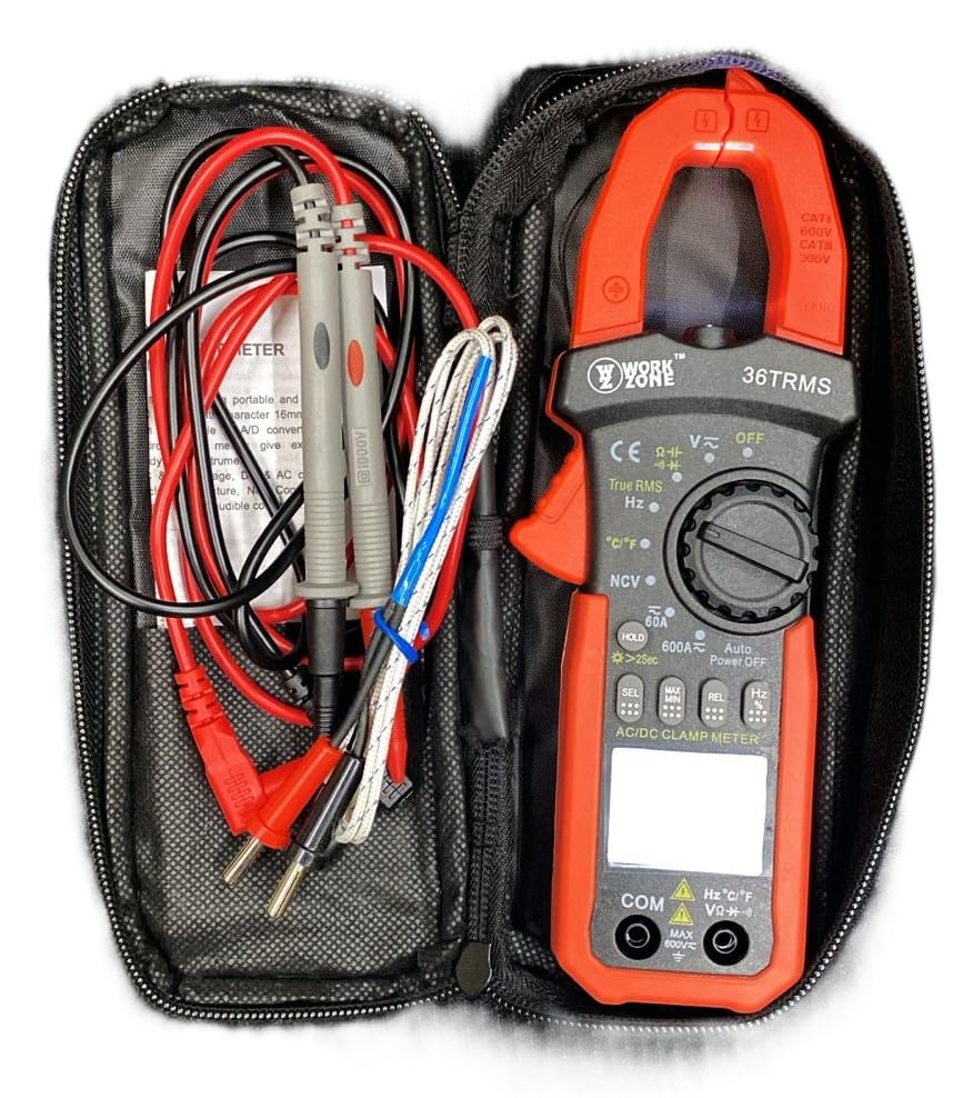
The Skyking WORKZONE 36TRMS Digital Clamp Meter, test leads, and temperature probe neatly organized within a black zippered carrying case. This illustrates how the product and its accessories are stored and transported.
4. Product Overview
The WORKZONE 36TRMS Digital Clamp Meter offers a range of features for comprehensive electrical testing:
- 6000 counts digit LCD monitor with 16mm character height.
- Auto-range and auto power-off function (after 15 minutes of inactivity).
- Clamp opening size: 26mm for non-invasive current measurement.
- Measures DC Voltage (600mV~600V) and AC Voltage (6V~600V).
- Measures DC Current (60A~600A) and AC Current (True RMS) (60A~600A).
- Measures Resistance (600Ω~60MΩ) and Capacitance (6nF~60mF).
- Measures Frequency (9.999Hz~9.999MHz) and Duty Cycle (0.1%~99.9%).
- Temperature measurement: -20~1000°C / -4~1832°F.
- Non-Contact AC Voltage (NCV) detection for safety.
- Diode and audible continuity test functions.
- Data hold function to freeze readings.
- Backlight for easy reading in dark environments.
- Relative measurement (REL) function for zeroing readings.

A detailed close-up of the Skyking WORKZONE 36TRMS Digital Clamp Meter. The image highlights the rotary switch with various measurement functions, the LCD display showing '0.000', function buttons (HOLD, SEL, MAX/MIN, REL, Hz), and the input jacks at the bottom.
5. Setup
5.1 Battery Installation
- The meter requires 2x 1.5V 'AAA' batteries.
- Locate the battery compartment cover on the back of the meter.
- Open the cover, insert the batteries observing correct polarity (+ and - markings).
- Close the battery compartment cover securely.
5.2 Power On/Off
- To power on the meter, rotate the rotary switch from the 'OFF' position to any desired measurement function.
- To power off, rotate the switch back to the 'OFF' position.
- The meter features an auto power-off function after approximately 15 minutes of inactivity to conserve battery life.
5.3 Test Lead Connection
- For voltage, resistance, capacitance, frequency, duty cycle, diode, and continuity measurements, insert the red test lead into the 'VΩHz°C' input jack.
- Insert the black test lead into the 'COM' input jack.
- Ensure test leads are fully inserted and securely connected.
6. Operating Instructions
6.1 DC/AC Voltage Measurement
- Rotate the rotary switch to 'V~' for AC Voltage or 'V-' for DC Voltage.
- Connect the test leads in parallel to the circuit or component under test.
- Read the voltage value on the LCD display.
6.2 AC/DC Current Measurement (Clamp Jaw)
- Rotate the rotary switch to '60A~' or '600A~' for AC Current, or '60A-' or '600A-' for DC Current.
- Press the clamp trigger to open the jaws and clamp around a single conductor. Ensure the conductor is centered within the jaws.
- Read the current value on the LCD display.
6.3 Resistance Measurement
- Rotate the rotary switch to 'Ω'.
- Ensure the circuit or component is de-energized before measurement.
- Connect the test leads across the component to be measured.
- Read the resistance value on the LCD display.
6.4 Capacitance Measurement
- Rotate the rotary switch to 'F'.
- Ensure the capacitor is fully discharged before testing to prevent damage to the meter.
- Connect the test leads across the capacitor terminals.
- Read the capacitance value on the LCD display.
6.5 Frequency/Duty Cycle Measurement
- Rotate the rotary switch to 'Hz'.
- Connect the test leads to the signal source.
- Press the 'Hz' button to toggle between Frequency (Hz) and Duty Cycle (%) display.
6.6 Temperature Measurement
- Rotate the rotary switch to '°C/°F'.
- Connect the temperature probe to the input jacks.
- Place the probe tip on the object whose temperature is to be measured.
- Press the '°C/°F' button to switch between Celsius and Fahrenheit units.
6.7 Diode Test
- Rotate the rotary switch to 'Diode/Continuity'.
- Connect the red test lead to the anode and the black test lead to the cathode of the diode.
- The display will show the forward voltage drop. Reverse the leads; the display should show 'OL' for an open circuit.
6.8 Continuity Test
- Rotate the rotary switch to 'Diode/Continuity'.
- Connect the test leads across the circuit or component.
- An audible buzzer will sound if continuity is detected (typically resistance below approximately 50Ω).
6.9 Non-Contact AC Voltage (NCV) Detection
- Rotate the rotary switch to 'NCV'.
- Bring the NCV sensor (located at the top of the clamp meter) close to an AC voltage source.
- The meter will emit an audible beep and the NCV indicator light will flash if AC voltage is detected.
6.10 Data Hold Function
- Press the 'HOLD' button to freeze the current reading on the display. Press again to release the hold.
- Long press the 'HOLD' button to activate the backlight for improved visibility in low-light conditions.
6.11 Relative Measurement (REL)
- In a measurement mode, press the 'REL' button to zero the current reading. Subsequent measurements will be displayed relative to this zero point.
- Press the 'REL' button again to exit relative mode.
7. Maintenance
7.1 Cleaning
- Wipe the meter casing with a soft, damp cloth.
- Do not use abrasive cleaners, solvents, or harsh chemicals, as these may damage the casing or display.
7.2 Battery Replacement
- When the low battery indicator appears on the LCD, replace the batteries promptly to ensure accurate readings.
- Follow the battery installation steps outlined in Section 5.1.
- Dispose of used batteries according to local regulations.
7.3 Storage
- When not in use for extended periods, store the meter in a cool, dry place.
- Avoid direct sunlight, extreme temperatures, and high humidity.
- It is recommended to remove batteries if storing for a very long time to prevent leakage.
8. Troubleshooting
- No Display or Faint Display: Check battery installation. If the low battery indicator is on, replace the batteries.
- Incorrect Readings: Ensure the correct function is selected for the measurement. Verify test lead connections are secure and in the correct input jacks. For resistance or capacitance, ensure the circuit is de-energized. For current, ensure only a single conductor is clamped within the jaws.
- "OL" Display: This indicates an over-range condition or an open circuit. If measuring resistance, it means the resistance is too high or the circuit is open. If measuring voltage or current, the value exceeds the selected range; switch to a higher range if available.
- No Continuity Beep: The resistance of the circuit or component is too high, or there is an open circuit.
9. Specifications
| Parameter | Value |
|---|---|
| Brand | Skyking |
| Model Number | Workzone 36 TRMS |
| Measurement Type | Digital Clamp Meter |
| Display | 6000 counts digit LCD |
| Clamp Opening Size | 26mm |
| DC Voltage Range | 600mV ~ 600V |
| AC Voltage Range | 6V ~ 600V |
| DC Current Range | 60A ~ 600A |
| AC Current Range (True RMS) | 60A ~ 600A |
| Resistance Range | 600Ω ~ 60MΩ |
| Capacitance Range | 6nF ~ 60mF |
| Frequency Range | 9.999Hz ~ 9.999MHz |
| Duty Cycle | 0.1% ~ 99.9% |
| Temperature Range | -20°C ~ 1000°C / -4°F ~ 1832°F |
| Over-range Indication | "OL" |
| Negative Polarity Indication | Automatic "-" display |
| Low Battery Indication | Yes |
| Auto Power Off | Approx. 15 minutes |
| Power Supply | 2 x 1.5V "AAA" batteries |
| Operating Temperature | 0°C ~ 40°C (relative humidity <85%) |
| Storage Temperature | -10°C ~ 50°C (relative humidity <85%) |
| Guaranteed Precision Temp. | 23±5°C (relative humidity <70%) |
| Dimensions (H x W x D) | 207 x 75 x 37 mm |
| Weight | Approx. 280g (including battery) |
| Safety Rating | CAT II 600V or CAT III 300V |
10. Warranty & Support
For warranty information or technical support regarding your Skyking WORKZONE 36TRMS Digital Clamp Meter, please contact Skyking Instruments directly. Refer to your purchase documentation or the manufacturer's official website for specific warranty terms, conditions, and contact details.