1. Introduction
The DUOYI DY4100B is a professional digital earth resistance tester designed for measuring earth resistance and earth voltage. It is widely used in electrical power systems, telecommunications, meteorology, oil fields, construction, and industrial electrical equipment for earth resistance testing. This manual provides essential information for the safe and correct operation of the device.
2. Safety Information
Please read and understand all safety warnings and operating instructions before using this instrument. Failure to do so may result in injury or damage to the meter or equipment under test.
- Always ensure the instrument is in good working condition before use.
- Do not use the instrument in explosive atmospheres or in the presence of flammable gases or dust.
- Avoid contact with live circuits during testing.
- Ensure all test leads are properly connected and in good condition.
- Replace batteries promptly when the low battery indicator appears.
- Do not exceed the maximum input ratings specified for the instrument.
- The instrument can withstand 300V AC for 1 minute on earth voltage and 200V AC for 10 seconds on earth resistance for overload protection.
3. Package Contents
Verify that all items listed below are present and undamaged. If any items are missing or damaged, contact your supplier.
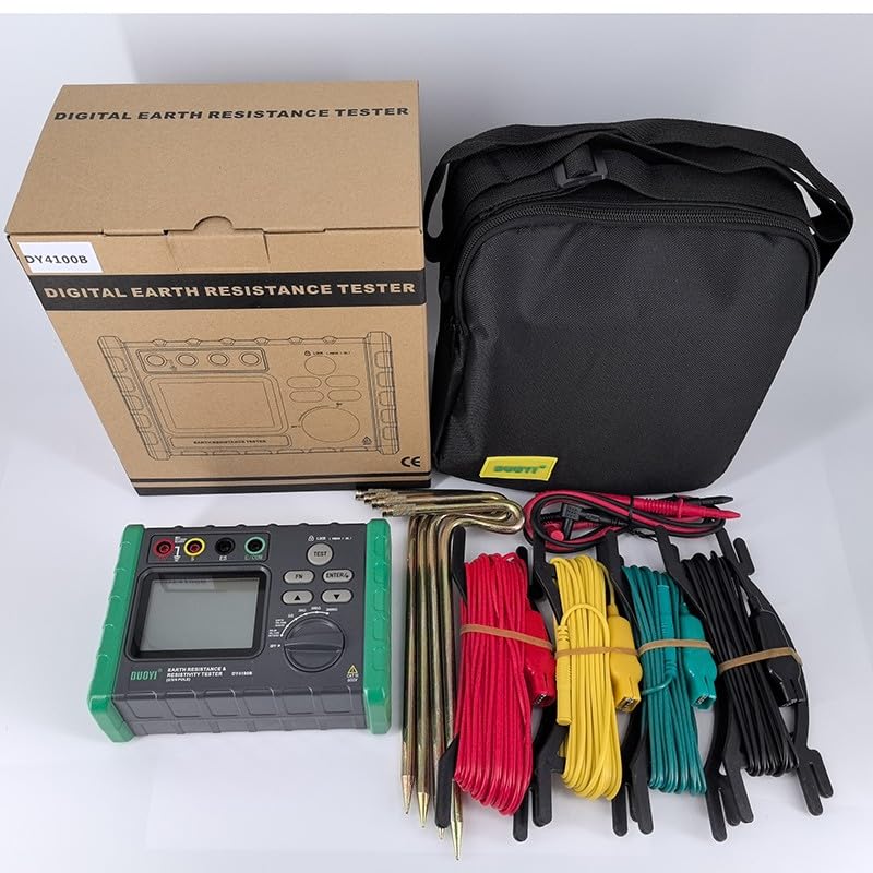
Figure 1: Complete DUOYI DY4100B Earth Resistance Tester kit. This image shows the main unit, a carrying bag, test leads (red, yellow, green, black), and earth rods.
- DUOYI DY4100B Earth Resistance Tester Unit
- Test Leads (Red, Yellow, Green, Black)
- Auxiliary Earth Rods
- Carrying Bag
- User Manual (this document)
- Note: 6 x 1.5V AA batteries are required but not included.
4. Product Overview
The DUOYI DY4100B features a robust design with a clear LCD display and intuitive controls for various measurement functions.
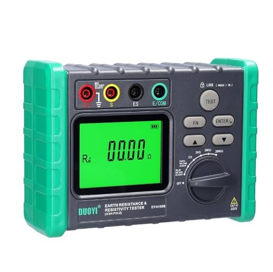
Figure 2: Front panel of the DUOYI DY4100B. This image highlights the 3 1/2 digit LCD, the rotary switch for function selection, input terminals (E, S, ES, E/COM), and control buttons (TEST, FN, ENTER, LOCK).
4.1 Key Components
- LCD Display: 3 1/2 digit display for showing measurement readings and indicators.
- Function Rotary Switch: Used to select measurement modes (OFF, Earth Voltage, Earth Resistance ranges: 20Ω, 200Ω, 2000Ω).
- Input Terminals:
- E (Earth): Main earth terminal.
- S (Sense): Potential electrode terminal.
- ES (Earth Sense): Auxiliary earth electrode terminal.
- E/COM (Common): Common terminal for earth voltage measurement.
- Buttons:
- TEST: Initiates an earth resistance measurement.
- FN: Function button (may switch between different display modes or settings).
- ENTER: Confirms selections.
- LOCK: Locks the display reading.
5. Setup
5.1 Battery Installation
- Ensure the instrument is turned OFF.
- Locate the battery compartment cover on the back of the unit.
- Open the cover and insert 6 x 1.5V AA batteries, observing correct polarity.
- Close the battery compartment cover securely.
5.2 Connecting Test Leads and Earth Rods (3-Pole Method Example)
For accurate earth resistance measurements, proper connection of test leads and auxiliary earth rods is crucial.
- Connect the green test lead to the E terminal on the meter and to the earth electrode under test.
- Connect the yellow test lead to the S terminal on the meter and to the potential auxiliary earth rod (P1).
- Connect the red test lead to the ES terminal on the meter and to the current auxiliary earth rod (C1).
- Drive the auxiliary earth rods (P1 and C1) into the ground in a straight line from the earth electrode under test, typically 5-10 meters apart, ensuring good contact with the soil.
Note: Refer to specific testing standards (e.g., IEEE 81) for detailed electrode placement guidelines for different measurement methods (2-pole, 3-pole, 4-pole). The DY4100B supports 3-pole and 2-pole measurements.
6. Operating Instructions
6.1 Powering On/Off
- To power on, rotate the function switch from OFF to the desired measurement range (e.g., Earth Voltage or a resistance range).
- To power off, rotate the function switch back to OFF.
6.2 Earth Voltage Measurement
- Connect the test leads: Connect the green lead to the E terminal and the black lead to the E/COM terminal.
- Rotate the function switch to the "Earth Voltage" position (0-30V range).
- The display will show the measured earth voltage. If the voltage is too high, the measurement may be inaccurate or unsafe. Ensure the voltage is within the safe operating range before proceeding with resistance measurements.
6.3 Earth Resistance Measurement (3-Pole Method)
- Ensure the earth voltage is within acceptable limits (ideally close to 0V) before proceeding.
- Connect the test leads and auxiliary earth rods as described in Section 5.2.
- Rotate the function switch to the desired earth resistance range (20Ω, 200Ω, or 2000Ω). Start with the highest range (2000Ω) if the resistance value is unknown.
- Press the TEST button to initiate the measurement. The display will show the earth resistance value.
- If the reading is "OL" (Overload), switch to a higher range. If the reading is very low, switch to a lower range for better resolution.
- Press the LOCK button to hold the current reading on the display. Press again to release.
- After measurement, rotate the function switch to OFF and disconnect the test leads.
6.4 Earth Resistance Measurement (2-Pole Method)
The 2-pole method is typically used for measuring the resistance of conductors or for quick checks where a known good earth reference is available.
- Connect the green test lead to the E terminal and to the earth electrode under test.
- Connect the red test lead to the ES terminal and to a known good earth reference (e.g., a water pipe, building ground).
- Rotate the function switch to the desired earth resistance range.
- Press the TEST button to initiate the measurement.
- Read the value on the display.
7. Maintenance
7.1 Battery Replacement
When the low battery indicator (12V battery missing on LCD, or LED red backlight off for 1.5V battery missing) appears on the display, replace all 6 x 1.5V AA batteries immediately to ensure accurate measurements.
- Turn off the instrument.
- Open the battery compartment cover.
- Remove the old batteries and dispose of them according to local regulations.
- Insert new 1.5V AA batteries, ensuring correct polarity.
- Close the battery compartment cover securely.
7.2 Cleaning and Storage
- Clean the instrument with a soft, damp cloth. Do not use abrasive cleaners or solvents.
- Store the instrument in a dry, cool place, away from direct sunlight and extreme temperatures.
- If storing for an extended period, remove the batteries to prevent leakage.
8. Troubleshooting
| Problem | Possible Cause | Solution |
|---|---|---|
| Instrument does not power on. | Dead or incorrectly installed batteries. | Check battery polarity, replace batteries. |
| "OL" displayed during resistance measurement. | Resistance value exceeds selected range; poor contact with earth rods. | Switch to a higher resistance range; ensure earth rods are firmly in the ground and connections are secure. |
| Unstable or fluctuating readings. | High earth voltage; poor connections; dry soil. | Check earth voltage first; ensure all connections are tight; moisten the soil around earth rods if dry. |
| Low battery indicator (LCD 12V missing / LED red backlight off). | Batteries are low. | Replace all 6 x 1.5V AA batteries. |
9. Specifications
| Parameter | Value |
|---|---|
| Earth Resistance Measurement Range | 0-2000Ω |
| Earth Resistance Accuracy | ±(2% + 3 digits) for 0-20Ω, ±(2% + 3 digits) for 0-200Ω, ±(2% + 3 digits) for 0-2000Ω |
| Earth Voltage Measurement Range | 0-30V AC |
| Earth Voltage Accuracy | ±(3% + 5 digits) |
| Resolution | 0.01Ω |
| Withstand Voltage (Circuit to Outer Casing) | AC 500V for 1 minute |
| Display | 3 1/2 digit LCD |
| Low Battery Warning | "12V battery missing" on LCD; LED red backlight off for 1.5V battery missing. |
| Overload Protection (Earth Voltage) | 300V AC for 1 minute |
| Overload Protection (Earth Resistance) | 200V AC for 10 seconds |
| Power Source | 6 x 1.5V AA batteries |
| Dimensions | 150mm x 100mm x 70mm |
| Weight (without batteries) | 680g |
| Manufacturer | DUOYI |
| Origin | Turkey |
10. Warranty and Support
DUOYI products are designed and manufactured to the highest quality standards. For warranty information, technical support, or service inquiries, please contact your local distributor or the point of purchase. Keep your purchase receipt as proof of purchase.