1. Introduction
This manual provides detailed instructions for the setup, operation, maintenance, and troubleshooting of your HCJYC Wi-Fi Developer Board for Flipper Zero. This kit enhances your Flipper Zero with wireless capabilities and provides comprehensive protection through its included accessories. Please read this manual carefully before use to ensure proper functionality and longevity of your device.
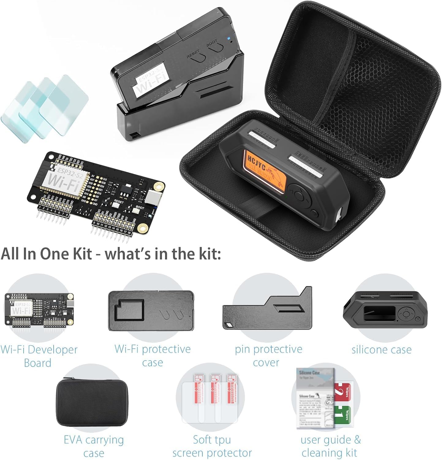
Image 1.1: The HCJYC Wi-Fi Developer Board and its protective case.
2. What's in the Box
Your HCJYC Wi-Fi Developer Board kit includes the following components:
- 1 x ESP32 Wi-Fi Developer Board for Flipper Zero
- 1 x Wi-Fi Board Protective Case Set (includes pin cover)
- 1 x Silicone Protective Cover for Flipper Zero
- 3 x Screen Protectors
- 1 x EVA Carrying Bag
Note: The Flipper Zero device is not included in this kit.

Image 2.1: Overview of all items included in the kit.
3. Setup
3.1 Installing the Wi-Fi Developer Board
- Power Off Flipper Zero: Before attaching the Wi-Fi Developer Board, ensure your Flipper Zero is completely powered off to prevent potential damage.
- Align the Board: Carefully align the pins of the Wi-Fi Developer Board with the GPIO pins on your Flipper Zero.
- Gently Connect: Press the Wi-Fi Developer Board firmly but gently onto the Flipper Zero until it is securely seated.

Image 3.1: The Wi-Fi Developer Board securely connected to the Flipper Zero.
3.2 Assembling the Protective Case
The Wi-Fi Board Protective Case is designed for easy, tool-free assembly.
- Insert the Board: Place the Wi-Fi Developer Board (with or without the Flipper Zero attached) into the bottom half of the protective case.
- Attach the Top Cover: Snap the top cover of the protective case onto the bottom half. Ensure all edges align and click into place for a secure fit. The PC cap provides 360-degree protection and prevents accidental button presses.

Image 3.2: The PC cap being installed, providing protection for the pins and USB-C port.
3.3 Applying Screen Protectors
The kit includes three screen protectors for your Flipper Zero display.
- Clean the Screen: Use a microfiber cloth to thoroughly clean the Flipper Zero screen, removing any dust or smudges.
- Peel and Align: Carefully peel off the backing of a screen protector and align it with the Flipper Zero's screen.
- Apply: Gently lay the screen protector onto the screen, smoothing out any air bubbles from the center outwards.
4. Operating the Wi-Fi Developer Board
Once installed, the Wi-Fi Developer Board integrates with your Flipper Zero, enabling Wi-Fi connectivity and advanced development capabilities.
4.1 Basic Functionality
- The board provides Wi-Fi connectivity, allowing your Flipper Zero to interact with Wi-Fi networks.
- It can be used for various development tasks, including network analysis and custom firmware flashing.
- The integrated ESP32-S2 module offers robust performance for Wi-Fi related applications.
4.2 Firmware and Development
The Wi-Fi Developer Board is compatible with various open-source firmware projects. Users can connect the Flipper Zero with the attached Wi-Fi board to a computer via USB-C for debugging and flashing custom firmware.
- Refer to online communities and official Flipper Zero documentation for guides on installing and utilizing specific firmware (e.g., Marauder firmware).
- The USB-C port on the board allows for direct communication with a development environment.
4.3 Heat Management
The protective case features a window-like cutout design to facilitate effective heat radiation from the Wi-Fi Developer Board, ensuring optimal performance without sacrificing signal integrity.

Image 4.1: The case design allows for efficient heat dissipation from the Wi-Fi module.
5. Maintenance
5.1 Cleaning
- Wi-Fi Developer Board: Use a dry, soft brush or compressed air to remove dust from the board and its pins. Avoid liquid cleaners.
- Protective Cases: The Wi-Fi Board Protective Case and Silicone Protective Cover can be wiped clean with a damp cloth. Ensure they are completely dry before reassembling.
- Screen Protectors: Clean with a soft, lint-free cloth.
5.2 Silicone Protective Cover
The 360-degree front-and-back silicone case provides rugged protection for your Flipper Zero, including hard-to-protect areas like the iButton port.

Image 5.1: Flipper Zero with the Wi-Fi Developer Board, encased in the silicone protective cover.
5.3 Storage
When not in use, store the Wi-Fi Developer Board and Flipper Zero in the provided EVA Carrying Bag to protect them from dust, scratches, and impacts.
6. Troubleshooting
- Board Not Detected: Ensure the Flipper Zero was powered off before installation and that the Wi-Fi Developer Board is securely seated on the GPIO pins. Try re-seating the board.
- Wi-Fi Connectivity Issues: Verify that the correct firmware is installed and configured for Wi-Fi operations. Check network settings and ensure the Flipper Zero is within range of a Wi-Fi signal.
- SD Card Compatibility (for Marauder firmware): Some users have reported issues with certain SD cards not saving files when using specific firmware like Marauder. If you encounter this, try using a different brand or capacity of microSD card. SanDisk and Samsung Evo cards are generally recommended, but compatibility can vary.
- Physical Damage: If the board or Flipper Zero is dropped, inspect for any visible damage. The protective cases are designed to mitigate impact, but severe drops can still cause issues.
7. Specifications
| Brand | HCJYC |
| Connectivity Technology | Wi-Fi |
| Compatible Devices | Flipper Zero |
| CPU Manufacturer | Espressif |
| Processor Brand | Espressif |
| Operating System | Linux (compatible) |
| Total USB Ports | 1 (USB-C for development/debugging) |
| ASIN | B0FT89TNCL |
| GTIN/UPC | 739505665789 |
8. Warranty
The HCJYC Wi-Fi Developer Board for Flipper Zero comes with a 1-year manufacturer's warranty. This warranty covers defects in materials and workmanship under normal use. It does not cover damage caused by misuse, accidents, unauthorized modifications, or improper installation.
Please retain your proof of purchase for warranty claims.
9. Support
For technical assistance, troubleshooting, or warranty inquiries, please contact HCJYC customer support through the platform where you purchased the product. You may also visit the HCJYC Store on Amazon for additional resources and contact information.