Introduction
Thank you for choosing the Acewelder MIG140PRO-HM 3-in-1 Welding Machine. This versatile 140A welder is designed for Flux Core Gasless MIG, LIFT TIG, and Stick (MMA) welding, suitable for various metals and alloys. It features a portable IGBT inverter, synergic control, and an LED display for enhanced user experience. This manual provides essential information for safe and effective operation, setup, maintenance, and troubleshooting.
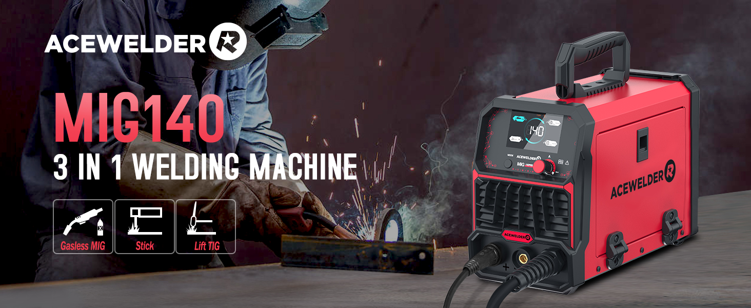
Image: The Acewelder MIG140PRO-HM 3-in-1 Welding Machine, highlighting its capabilities for Gasless MIG, Stick, and Lift TIG welding.
Safety Information
Always prioritize safety when operating welding equipment. Read and understand all safety warnings and instructions before use. Failure to do so may result in serious injury or death.
- Wear appropriate personal protective equipment (PPE), including a welding helmet, gloves, and protective clothing.
- Ensure adequate ventilation to avoid inhaling welding fumes.
- Keep flammable materials away from the welding area.
- Always disconnect power before performing maintenance or adjustments.
- The machine is equipped with overload and overheating protection systems.
Image: Diagram illustrating the safety features of the welding machine, including overheating protection, overload protection, water rating, and electrostatic coating.
Package Contents
Upon unpacking, verify that all items listed below are present and undamaged:
- 140Pro MIG Welder Unit
- MIG Torch
- Electrode Holder
- Ground Clamp
- Brush
- 0.5kg 0.8mm Flux Cored Wire
- 0.030" / 0.035" Contact Tips & Nozzles
- Professional Welding Helmet

Image: Visual representation of the Acewelder MIG140PRO-HM welding machine and its included accessories, such as the welding helmet, ground clamp, electrode holder, brush/hammer, flux cored wire, contact tips, and nozzles.
Setup
1. Power Connection
Connect the welder to a standard 110V AC power outlet. Ensure the power switch on the rear of the unit is in the OFF position before plugging in.
2. Wire Installation (Flux Core MIG)
- Open the side panel of the welder to access the wire feed mechanism.
- Mount the 0.5kg 0.8mm flux cored wire spool onto the spindle.
- Thread the wire through the guide and into the drive rollers.
- Adjust the tension of the drive rollers to ensure smooth wire feeding without crushing the wire.
- Close the side panel securely.

Image: Diagram showing the internal compartment for installing flux core welding wire, indicating compatibility with 0.030" and 0.035" wire sizes.
3. Connecting Welding Accessories
- MIG Welding: Connect the MIG torch to the appropriate port. Ensure the ground clamp is securely attached to the workpiece.
- Stick (MMA) Welding: Connect the electrode holder to the positive (+) terminal and the ground clamp to the negative (-) terminal.
- LIFT TIG Welding: Connect the TIG torch (not included, but compatible) to the negative (-) terminal and the ground clamp to the positive (+) terminal.

Image: Visual guide demonstrating the connection points for Gassless MIG, Stick, and Lift TIG welding modes on the Acewelder MIG140PRO-HM.
Operating Instructions
1. Power On and Mode Selection
Turn on the power switch located on the rear of the unit. The LED display will illuminate. Press the "MODE" button on the front panel to cycle through the available welding modes: MMA (Stick), TIG (LIFT TIG), and Flux (Flux Core MIG).

Image: Close-up of the digital LED screen display on the welder, showing voltage, current, and mode selection indicators.
2. Synergic Control (MIG Mode)
In Flux Core MIG mode, the machine features synergic control. After selecting the diameter of the welding wire (e.g., FLUX/0.8 or FLUX/0.9), the welding voltage and wire feed speed will automatically adjust to optimal settings. This simplifies operation, especially for beginners.

Image: Illustration of the synergic control feature, indicating automatic matching of voltage and wire feed speed.
3. Amperage Adjustment
Use the control knob to adjust the amperage (A) according to your welding requirements and material thickness. The LED display will show the current amperage setting. For optimal results, refer to welding charts for specific material and wire/electrode combinations.
4. Welding Helmet Operation
The included professional welding helmet features auto-darkening technology. Ensure the helmet is properly fitted and the sensitivity/delay settings are adjusted for your environment. The helmet will automatically darken upon arc ignition to protect your eyes.

Image: Close-up of the auto-darkening welding helmet, highlighting features like true color, fast darkening, PP-strong material, and anti-blue ray protection.
Maintenance
Regular maintenance ensures the longevity and optimal performance of your welding machine.
- Cleaning: Periodically clean the exterior of the welder with a dry cloth. Ensure ventilation openings are free from dust and debris.
- Wire Feed Mechanism: Inspect the wire feed rollers and liner for wear or blockages. Clean as necessary to prevent wire feeding issues.
- Torch and Cables: Check welding cables and the torch for damage, cuts, or loose connections. Replace worn parts immediately.
- Storage: Store the welder in a dry, clean environment when not in use.
Troubleshooting
This section addresses common issues you might encounter. For problems not listed here, contact customer support.
- No Power: Check the power cord connection, wall outlet, and the welder's power switch. Ensure the circuit breaker has not tripped.
- Poor Arc Start/Stability: Verify proper ground clamp connection, check electrode/wire condition, and ensure correct amperage settings for the material.
- Wire Feeding Issues (MIG): Inspect the wire spool for tangles, check drive roller tension, and ensure the contact tip is not clogged.
- Overheating Indicator: If the overheating indicator illuminates, stop welding and allow the machine to cool down. Ensure adequate ventilation around the unit.
Specifications
| Feature | Specification |
|---|---|
| Model Number | MIG140PRO-HM |
| Welding Modes | Flux Core Gasless MIG, MMA (Stick), LIFT TIG |
| Input Voltage | 110 Volts AC |
| Max Amperage | 140A |
| Max Plate Thickness | 4.0mm (5/32") |
| Compatible Wire Sizes | 0.030", 0.035", 0.040" Flux Core |
| Wire Spool Capacity | 2.2 pounds |
| Item Weight | 18.61 pounds |
| Package Dimensions | 18.25 x 16.5 x 13.2 inches |
| Manufacturer | ACEWELDER |
Warranty and Support
The Acewelder MIG140PRO-HM welding machine is covered by a two-year warranty. During this period, Acewelder guarantees against any manufacturing defects or issues with the welding machine. For warranty claims, technical support, or any inquiries, please contact Acewelder customer service.