1. Introduction
This manual provides instructions for the proper installation, operation, and maintenance of the Generic Control Box Lock with Keys, model 096-1002. This product is a genuine OEM replacement part designed for use in various control boxes, commonly found in food service equipment and vending machines. Please read this manual thoroughly before installation and use to ensure safe and efficient operation.
2. Safety Information
- Always ensure the power to the control box is disconnected before attempting installation or maintenance.
- Wear appropriate personal protective equipment (PPE) such as gloves and eye protection during installation.
- Handle keys with care to prevent bending or breaking.
- Keep spare keys in a secure location, separate from the lock.
- If the lock mechanism appears damaged, do not attempt to force it. Replace the unit if necessary.
3. Package Contents
Verify that all items are present in the package:
- 1 x Control Box Lock (Model 096-1002)
- 2 x Keys
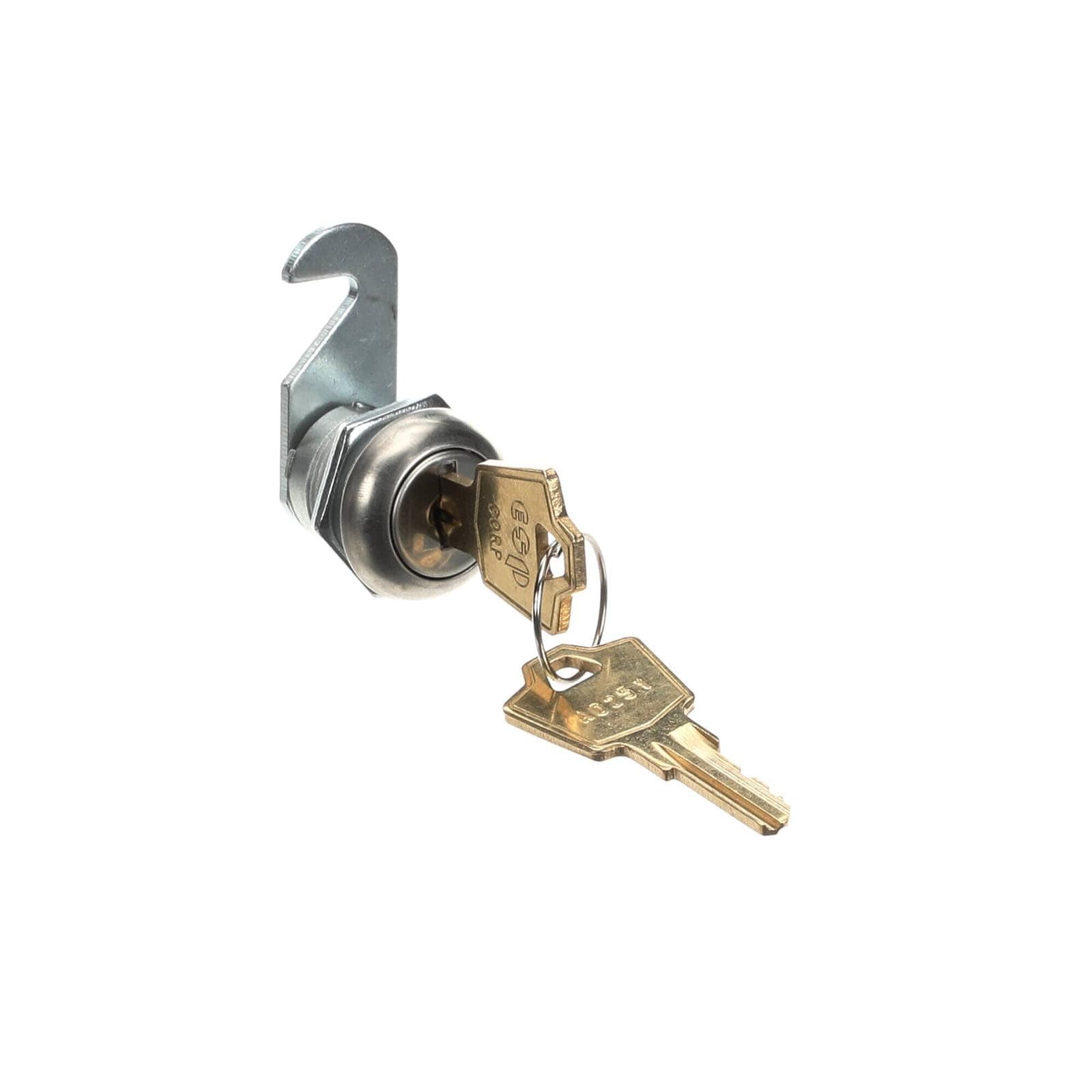
Image 3.1: The control box lock with its accompanying keys.
4. Setup and Installation
This lock is designed for straightforward replacement in compatible control boxes. The exact installation procedure may vary slightly depending on the specific control box design. Always refer to the equipment's original service manual if available.
- Prepare the Control Box: Ensure the control box is powered off and disconnected from any electrical source. Open the control box door or panel to access the existing lock mechanism.
- Remove Old Lock: Carefully remove the old lock. This typically involves unscrewing a retaining nut from the inside of the control box panel and detaching any cam or latching mechanism. Keep any washers or spacers for potential reuse.
- Insert New Lock: Insert the new 096-1002 lock cylinder through the opening in the control box panel from the outside.
- Secure the Lock: From the inside of the control box, place any necessary washers or spacers, then thread and tighten the retaining nut onto the back of the lock cylinder. Ensure the lock is snug but do not overtighten, which could damage the lock or panel.
- Attach Cam/Latching Mechanism: Attach the appropriate cam or latching mechanism to the square shaft at the back of the lock cylinder, securing it with the provided screw or clip. Ensure the cam rotates freely and engages properly with the control box frame when the lock is turned.
- Test Operation: Before closing the control box, insert a key and test the locking and unlocking action. Ensure the cam fully engages and disengages.

Image 4.1: The lock cylinder with a key, illustrating the components for installation.
5. Operating Instructions
To operate the control box lock:
- To Lock: Insert the key into the keyway. Turn the key clockwise (typically 90 degrees) until the cam engages with the control box frame, securing the door or panel. Remove the key.
- To Unlock: Insert the key into the keyway. Turn the key counter-clockwise (typically 90 degrees) until the cam disengages from the control box frame, allowing the door or panel to open. Remove the key.
Always ensure the key is fully inserted before turning to prevent damage to the key or lock mechanism.
6. Maintenance
Regular maintenance helps ensure the longevity and smooth operation of your lock:
- Cleaning: Periodically wipe the exterior of the lock with a clean, dry cloth to remove dust and grime. Avoid using harsh chemicals or abrasive cleaners.
- Lubrication: If the key becomes difficult to turn, apply a small amount of graphite lubricant or a silicone-based lock lubricant into the keyway. Do not use oil-based lubricants as they can attract dirt and gum up the mechanism.
- Key Care: Do not use keys for purposes other than operating the lock. Avoid bending or forcing keys.
7. Troubleshooting
| Problem | Possible Cause | Solution |
|---|---|---|
| Key will not insert fully. | Obstruction in keyway; incorrect key. | Check for debris in the keyway. Ensure you are using the correct key for this lock. |
| Key turns but lock does not engage/disengage. | Cam/latching mechanism improperly installed or damaged. | Re-check the installation of the cam on the back of the lock cylinder. Ensure it is securely fastened and aligned. If damaged, replace the cam or lock. |
| Key is difficult to turn. | Lack of lubrication; minor internal obstruction. | Apply graphite or silicone-based lock lubricant into the keyway. Work the key gently. Do not force. |
| Lock is loose in the panel. | Retaining nut is loose. | Tighten the retaining nut on the back of the lock cylinder from inside the control box. |
8. Specifications
- Type: Food Service Supply
- Manufacturer Part Number (MPN): 096-1002
- Model Number (Manufacturer): CKD-Generic-TD2045
- Brand: Generic
- Material: High-quality materials for durability and performance
- ASIN: B0FSYSRGGW
9. Warranty and Support
This product is backed by a money-back guarantee, ensuring quality and customer satisfaction. If you encounter any issues or have questions regarding compatibility or installation, please contact the seller for assistance.
For further support, refer to the contact information provided by your retailer or on the product packaging.


