1. Introduction
This manual provides detailed instructions for the safe and effective operation of the ZLYMTXHW BSIDE ZT-X 102A Digital Multimeter. This True RMS auto-ranging multimeter is designed for measuring DC/AC voltage, DC/AC current, resistance, capacitance, frequency, temperature, and for non-contact voltage (NCV) detection. Please read this manual thoroughly before use and retain it for future reference.
2. Safety Information
To ensure safe operation, observe the following safety precautions:
- Always adhere to local and national safety codes.
- Do not apply voltage or current that exceeds the maximum specified limits for the meter.
- Exercise extreme caution when working with voltages above 30V AC RMS, 42V peak, or 60V DC. These voltages pose a shock hazard.
- Before measuring current, ensure the circuit is de-energized and the meter is connected in series.
- Before measuring resistance, capacitance, or diodes, disconnect power to the circuit and discharge all high-voltage capacitors.
- Replace the battery immediately when the low battery indicator appears to ensure accurate readings.
- Do not operate the meter if it appears damaged or if the casing is open.
- Use only the specified replacement parts when servicing the meter.
3. Product Overview
The ZT-X 102A Digital Multimeter features an EBTN (Enhanced Black Twisted Nematic) display for clear visibility and an ergonomic design for comfortable handling.
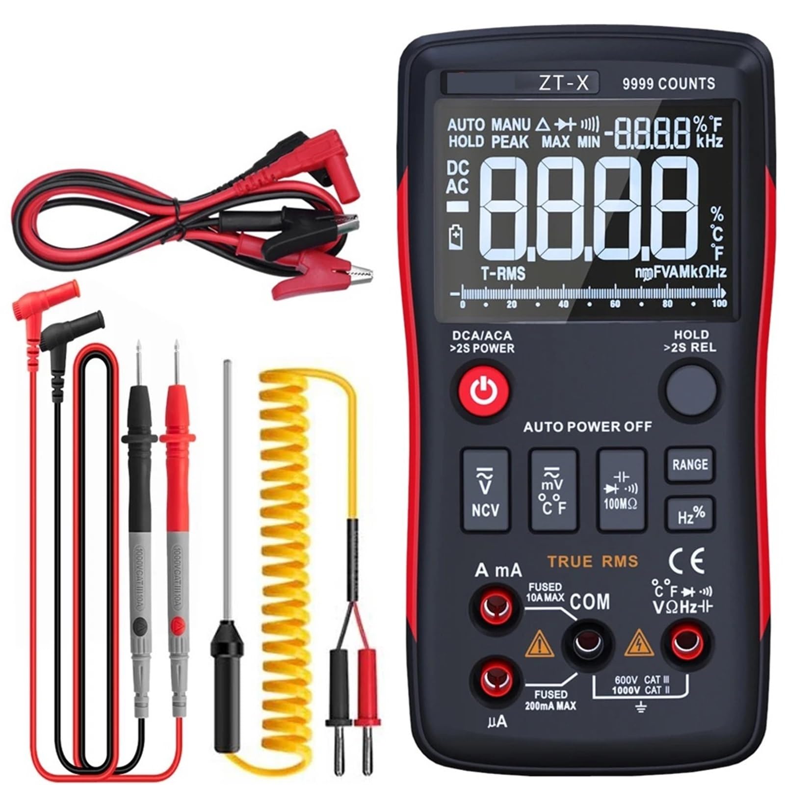
Figure 3.1: Front view of the ZLYMTXHW BSIDE ZT-X 102A Digital Multimeter, showing the EBTN display, function dial, and input jacks.
3.1 Key Components
- EBTN Display: High-contrast display for clear readings.
- Function Dial: Selects measurement modes.
- Input Jacks: Terminals for test leads (COM, VΩmA, 10A).
- Buttons: HOLD, RANGE, REL, Hz/%, NCV, etc. (specific buttons may vary slightly).
- NCV Sensor: For non-contact voltage detection.
4. Setup
4.1 Battery Installation
- Ensure the multimeter is turned off.
- Locate the battery compartment cover on the back of the meter.
- Use a screwdriver to remove the screw(s) securing the cover.
- Insert the required batteries (e.g., 2x AA or 9V, refer to the compartment label) observing correct polarity.
- Replace the battery compartment cover and secure it with the screw(s).
4.2 Connecting Test Leads
- Insert the black test lead into the "COM" (common) jack.
- For most measurements (voltage, resistance, capacitance, frequency, temperature), insert the red test lead into the "VΩmA" jack.
- For high current measurements (up to 10A), insert the red test lead into the "10A" jack.
5. Operating Modes
Turn the function dial to select the desired measurement mode. The meter features auto-ranging, simplifying operation by automatically selecting the appropriate range.
5.1 DC/AC Voltage Measurement
- Set the function dial to the V (DC) or V~ (AC) position.
- Connect the test leads in parallel to the circuit or component under test.
- Read the voltage value on the display.
5.2 DC/AC Current Measurement
- Safety Warning: Ensure the circuit is de-energized before connecting the meter in series.
- Set the function dial to the A (DC) or A~ (AC) position.
- Connect the meter in series with the circuit. For currents up to 10A, use the 10A jack. For lower currents, use the VΩmA jack.
- Apply power to the circuit and read the current value.
5.3 Resistance Measurement (Ohm)
- Safety Warning: Disconnect power and discharge capacitors before measuring resistance.
- Set the function dial to the Ω position.
- Connect the test leads across the component.
- Read the resistance value.
5.4 Capacitance Measurement
- Safety Warning: Disconnect power and discharge capacitors before measuring capacitance.
- Set the function dial to the capacitance (usually indicated by a capacitor symbol) position.
- Connect the test leads across the capacitor.
- Read the capacitance value.
5.5 Temperature Measurement
- Set the function dial to the temperature (°C/°F) position.
- Connect the temperature probe (if included) to the appropriate input jacks (usually VΩmA and COM).
- Place the probe tip on the object whose temperature is to be measured.
- Read the temperature value.
5.6 Frequency (Hz) Measurement
- Set the function dial to the Hz position.
- Connect the test leads in parallel to the signal source.
- Read the frequency value.
5.7 Non-Contact Voltage (NCV) Detection
- Set the function dial to the NCV position.
- Move the NCV sensor (usually at the top of the meter) close to the conductor.
- The meter will indicate the presence of AC voltage through an audible beep and/or visual indicator.
6. Maintenance
6.1 Cleaning
Wipe the meter's casing with a damp cloth and a mild detergent. Do not use abrasives or solvents. Ensure the meter is dry before use.
6.2 Battery Replacement
When the low battery indicator appears on the display, replace the batteries as described in Section 4.1. Always use fresh batteries of the specified type.
6.3 Fuse Replacement (if applicable)
If the current measurement function fails, the fuse may need replacement. Refer to the meter's internal diagram or contact support for specific fuse types and replacement procedures. Always disconnect power and test leads before opening the meter for fuse replacement.
7. Troubleshooting
| Problem | Possible Cause | Solution |
|---|---|---|
| No display or dim display | Low or dead batteries | Replace batteries (Section 4.1) |
| Incorrect readings | Incorrect mode selection, poor test lead connection, or damaged test leads | Verify mode, check connections, replace test leads if damaged |
| Current measurement not working | Blown fuse | Replace fuse (Section 6.3) |
| NCV not detecting voltage | Voltage too low, or NCV sensor not close enough | Ensure voltage is within detectable range, move sensor closer to conductor |
8. Specifications
| Parameter | Range / Value |
|---|---|
| Operating Mode | Auto Range |
| Measuring Capacitance Range | Up to 10000µF |
| Measuring Resistance Range | Up to 10MΩ |
| DC Current | Up to 10A |
| AC Current | Up to 10A |
| DC Voltage | Up to 1000V |
| Display Type | Digital Display (EBTN) |
| AC Voltage | Up to 750V |
| True RMS | Yes |
| NCV Detection | Yes |
| Power Source | Batteries (type specified in manual/compartment) |
| Item Weight | 50 g |
| Dimensions | 1 x 1 x 1 cm (packaging dimensions, actual product dimensions may vary) |
Note: Specifications are subject to change without notice. Refer to the product label for the most accurate information.
9. Warranty and Support
For warranty information, technical support, or service inquiries, please contact your point of purchase or the manufacturer directly. Keep your purchase receipt as proof of purchase.
Manufacturer: ZLYMTXHW