
1. Introduction
This manual provides essential information for the safe and efficient installation, operation, and maintenance of your ZQFEE 4.2KW 24V Hybrid Solar Inverter. This device is designed to integrate solar power, utility grid power, and battery storage to provide a reliable power supply for various loads. It features a pure sine wave output, an integrated MPPT 100A charger, and supports both 12V and 24V battery modes, with a maximum load of 2300W in 12V mode and 4200W in 24V mode.
2. Safety Information
Please read all instructions and warnings carefully before installation and operation. Failure to follow these instructions may result in electric shock, fire, or severe injury.
- Installation must be performed by qualified personnel.
- Ensure all connections are secure and correctly polarized.
- Do not disassemble the inverter. There are no user-serviceable parts inside.
- Keep the inverter away from flammable materials and ensure adequate ventilation.
- Disconnect all power sources (solar, utility, battery) before performing any maintenance or wiring.
- Wear appropriate personal protective equipment (PPE) during installation.
3. Product Features
- Pure sine wave output inverter.
- Dual battery voltage modes: 2300W max load in 12V mode, 4200W max load in 24V mode.
- Integrated MPPT 100A solar charger with an operating voltage range of 55V~500V and an open circuit voltage of 500Voc.
- Supports simultaneous power supply to loads from solar energy and utility grid.
- AC input compatible with both mains power and generators.
- Automatic restart function upon restoration of mains power.
- Comprehensive protection against overload, over temperature, and short circuit.
- Intelligent battery charging design for optimized battery utilization.
- RS485 port for communication with Battery Management Systems (BMS).
- Cold start function.
- Adjustable charging current via LCD display based on battery requirements.
- Selectable utility grid input voltage range for different load types (household appliances/personal computers).
4. Package Contents
Upon unpacking, please verify that all components are present and undamaged. If any items are missing or damaged, contact your vendor immediately.
- ZQFEE 4.2KW 24V Hybrid Solar Inverter Unit
- User Manual
- Communication Cable (e.g., RS485)
- Mounting Hardware (screws, anchors)
5. Setup
5.1 System Connection Diagram
The diagram below illustrates the typical system connection for the ZQFEE Hybrid Solar Inverter, integrating solar panels, a generator or utility grid, a battery bank, and various home appliances.

Figure 5.1: This diagram shows the complete system setup. Solar power (Max. PV Array Power: 4000W, MPPT Voltage Range: 55~500V DC, Max. VOC: 500VDC) and a generator or utility grid can feed into the inverter. The inverter connects to a 12V or 24V lithium or lead-acid battery. The inverter provides a single-phase 230V output (2.3KW/4.2KW) to home appliances such as refrigerators, lights, laptops, and fans. The maximum charging current (AC charger + solar charger) is 100A.
5.2 Physical Installation
Select a suitable mounting location that is dry, well-ventilated, and protected from direct sunlight, rain, and dust. Ensure there is sufficient clearance around the inverter for proper airflow and cooling. Mount the inverter vertically on a sturdy wall using the provided mounting hardware.
5.3 Wiring Instructions
Before making any electrical connections, ensure all power sources are disconnected. Refer to the terminal labels on the inverter for correct wiring.
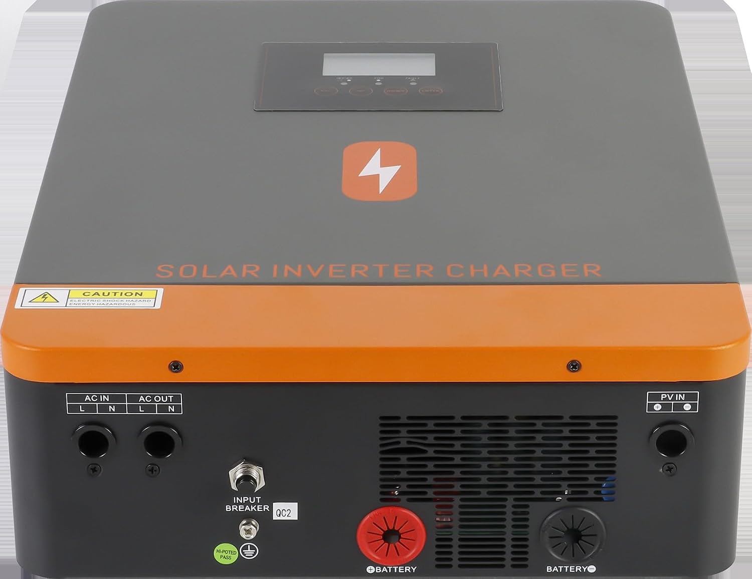
Figure 5.2: This image displays the rear panel of the solar inverter charger, showing various connection terminals. From left to right, there are AC IN (L, N) and AC OUT (L, N) terminals, an INPUT BREAKER, and terminals for BATTERY (+ and -) and PV IN (+ and -). A caution label regarding energy hazard is visible on the top left.
- Battery Connection: Connect the positive (+) and negative (-) terminals of your 12V or 24V battery bank to the corresponding BATTERY terminals on the inverter. Ensure correct polarity.
- PV Input: Connect the solar panel array's positive (+) and negative (-) leads to the PV IN terminals. Verify that the PV array's open circuit voltage and operating voltage range are within the inverter's specifications (55V~500V operating, 500Voc max).
- AC Input: Connect the utility grid or generator AC supply to the AC IN (L, N) terminals.
- AC Output: Connect your loads (home appliances) to the AC OUT (L, N) terminals.
- Grounding: Ensure the inverter is properly grounded according to local electrical codes.
6. Operating Instructions
6.1 Initial Power-Up
- After all connections are securely made, switch on the battery breaker first.
- Next, switch on the PV array breaker (if applicable).
- Finally, switch on the AC input breaker (if connecting to utility or generator).
- The inverter will perform a self-test and the LCD display will illuminate.
6.2 LCD Display and Settings
The inverter features an LCD display for monitoring system status and adjusting parameters. Use the navigation buttons to scroll through menus and select settings. Key adjustable settings include:
- Charging Current: Set the battery charging current according to your battery's specifications.
- AC Input Voltage Range: Select the appropriate input voltage range for your connected loads (e.g., household appliances or personal computers).
- Output Priority: Configure the power source priority (e.g., Solar first, Utility first, SBU - Solar-Battery-Utility).
6.3 Battery Compatibility and Activation
The inverter is compatible with multiple battery types, including AGM, GEL, FLD, LI (Lithium), SLD, and USER-defined settings. When solar energy is available, setting the battery type to 'LI' will activate the lithium battery after approximately 3 seconds.

Figure 6.1: This image illustrates the battery compatibility of the PowMr solar inverter. It shows icons for various battery types: AGM, GEL, FLD, LI (Lithium), SLD, and USER. A note indicates that when solar energy is present, setting the battery type to LIB will activate the lithium battery after 3 seconds. The inverter unit is shown mounted on a wall next to another PowMr device.
7. Maintenance
Regular maintenance ensures the longevity and optimal performance of your inverter. Always disconnect all power sources before performing any maintenance.
- Periodic Inspection: Check all wiring connections for tightness and signs of corrosion. Inspect the inverter casing for any physical damage.
- Cleaning: Keep the inverter's exterior clean and free of dust. Use a dry cloth for cleaning. Do not use liquid cleaners.
- Ventilation: Ensure the ventilation openings are clear of obstructions to allow for proper heat dissipation.
7.1 Cooling System
The inverter is equipped with internal cooling fans to maintain optimal operating temperature. Ensure these fans are not obstructed and are functioning correctly. Periodically check for dust accumulation on the fan grilles and clean as necessary.

Figure 7.1: This image shows the side view of the ZQFEE Hybrid Solar Inverter, highlighting the two cooling fans. These fans are crucial for dissipating heat and maintaining the inverter's operational efficiency and lifespan.
8. Troubleshooting
This section provides solutions to common issues you might encounter. For problems not listed here, contact technical support.
| Problem | Possible Cause | Solution |
|---|---|---|
| Inverter not powering on | No battery connection or low battery voltage; DC breaker off. | Check battery connections and voltage. Ensure DC breaker is on. |
| No AC output | Overload; Short circuit; Over temperature; AC output breaker off. | Reduce load. Check for short circuits. Allow inverter to cool. Check AC output breaker. |
| Battery not charging | PV input issue; AC input issue; Incorrect charging settings. | Check PV connections and voltage. Verify AC input. Adjust charging current settings via LCD. |
| Overload protection activated | Connected load exceeds inverter capacity. | Reduce the total load connected to the inverter. |
| Over temperature warning | Insufficient ventilation; High ambient temperature. | Ensure clear airflow around the inverter. Relocate to a cooler environment if necessary. |
9. Specifications
| Feature | Specification |
|---|---|
| Model Number | POW-HVM4.2K-24V-D (1005009242282127) |
| Output Type | SINGLE (Pure Sine Wave) |
| Output Frequency | 50HZ/60HZ |
| Max Load (12V Battery Mode) | 2300W |
| Max Load (24V Battery Mode) | 4200W |
| MPPT Operating Voltage Range | 55V~500V DC |
| Max. PV Array Open Circuit Voltage (VOC) | 500VDC |
| Max. PV Array Power | 4000W |
| Max Charging Current (MPPT) | 100A |
| Weight | 17.64 pounds (8KG) |
| Package Dimensions | 0.39 x 0.39 x 0.39 inches |
| Manufacturer | ZQFEE |
| Smart Device | Yes (WIFI remote monitoring optional) |
10. Warranty and Support
For warranty information and technical support, please refer to the documentation provided with your purchase or contact your vendor. Keep your purchase receipt as proof of purchase for warranty claims.