1. Introduction
This manual provides detailed instructions for the installation, configuration, and maintenance of your ASUS B760M MAX Gaming WiFi mATX Motherboard. Designed for Intel LGA 1700 processors, this motherboard features PCIe 5.0 x16, DDR5 memory support, multiple M.2 slots, Wi-Fi 6, and comprehensive connectivity options. Please read this manual thoroughly before proceeding with installation to ensure proper setup and optimal performance.

Image 1.1: The ASUS B760M MAX Gaming WiFi Motherboard alongside its retail packaging, showcasing the product and its branding.
2. Safety Information
Always observe the following safety precautions to prevent damage to the motherboard and injury to yourself:
- Electrostatic Discharge (ESD) Precautions: Always wear an anti-static wrist strap or frequently touch a grounded metal object (like the computer case) before handling components.
- Power Disconnection: Ensure the power supply is disconnected from the wall outlet before installing or removing any components.
- Component Handling: Handle components by their edges. Avoid touching pins or circuit paths.
- Ventilation: Ensure adequate ventilation within the computer case to prevent overheating.
- Professional Installation: If you are unsure about any installation steps, consult a qualified technician.
3. Package Contents
Verify that all items are present in your motherboard package. If any items are missing or damaged, contact your retailer.
- ASUS B760M MAX Gaming WiFi Motherboard
- User Manual / Quick Start Guide
- SATA 6Gb/s Data Cables (typically 2)
- M.2 Screw Package (for securing M.2 SSDs)
- Wi-Fi Antenna
- I/O Shield (if not pre-mounted)

Image 3.1: The motherboard shown with its typical accessories, including SATA cables, M.2 screws, Wi-Fi antenna, and the rear I/O panel shield, along with its dimensions.
4. Motherboard Layout
Familiarize yourself with the key components and connectors on the motherboard before installation.

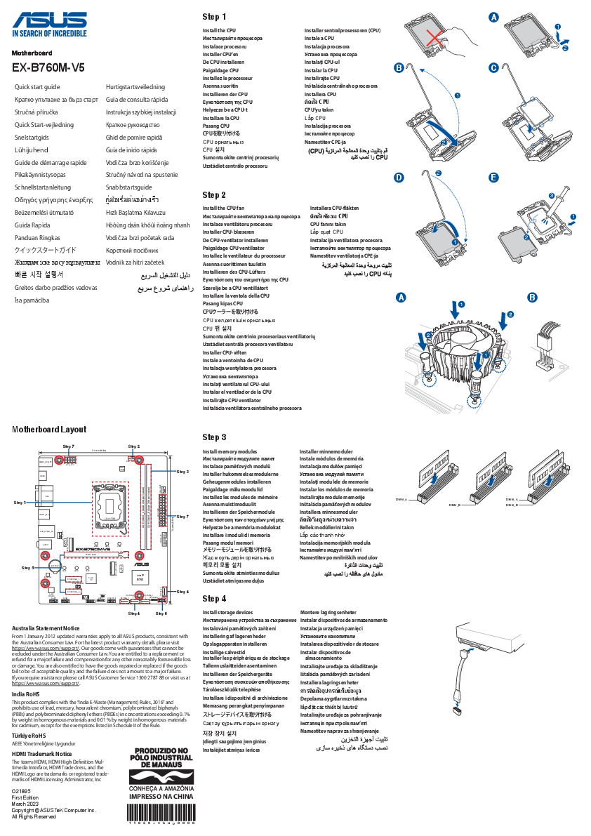
Image 4.1: A detailed top-down view of the motherboard, illustrating the placement of the CPU socket, DIMM slots, PCIe slots, M.2 slots, and various headers.
Key Components:
- CPU Socket (LGA 1700): Located centrally, designed for Intel Core 14th, 13th, and 12th Gen Processors.
- DDR5 DIMM Slots: Four slots for DDR5 memory modules, typically located to the right of the CPU socket.
- PCIe 5.0 x16 Slot: The primary slot for graphics cards, reinforced for durability (SafeSlot).
- PCIe 4.0 x16/x1 Slots: Additional slots for expansion cards.
- M.2 Slots: Three slots for high-speed NVMe SSDs.
- SATA 6Gb/s Ports: For connecting traditional SATA storage devices.
- Rear I/O Panel: Includes USB ports (10Gbps Type-A, 5Gbps Type-C), DisplayPort, HDMI, Wi-Fi antenna connectors, and audio jacks.
- Front Panel Headers: Connectors for your PC case's front panel USB ports, audio, power button, reset button, and indicator LEDs.
5. Setup and Installation
Follow these steps carefully to install your motherboard and essential components.
5.1. CPU Installation
- Locate the LGA 1700 socket on the motherboard.
- Open the CPU socket lever and lift the load plate.
- Carefully align the notches on your Intel LGA 1700 CPU with the keys on the socket. Ensure the triangular mark on the CPU aligns with the mark on the socket.
- Gently place the CPU into the socket. Do not force it.
- Lower the load plate and push down the lever until it locks into place.
- Apply thermal paste and install the CPU cooler according to its manufacturer's instructions.
5.2. Memory (RAM) Installation
- Locate the DDR5 DIMM slots. For optimal performance, refer to your motherboard's manual for recommended dual-channel configuration (usually slots A2 and B2 first).
- Open the clips at both ends of the DIMM slot.
- Align the notch on the DDR5 memory module with the key in the DIMM slot.
- Insert the memory module firmly into the slot until the clips snap into place. Ensure both clips are closed.
5.3. Storage Device Installation
M.2 SSD Installation:
- Locate an M.2 slot on the motherboard. Some slots may have a heatsink that needs to be removed first.
- Remove the M.2 standoff screw from the desired length position.
- Insert the M.2 SSD into the slot at a 30-degree angle.
- Gently push the SSD down and secure it with the M.2 screw.
- If applicable, reattach the M.2 heatsink.
SATA Drive Installation:
- Connect one end of a SATA data cable to a SATA 6Gb/s port on the motherboard.
- Connect the other end of the SATA data cable to your SATA HDD/SSD.
- Connect a SATA power cable from your power supply to the SATA HDD/SSD.
5.4. Expansion Card Installation (PCIe)
- Locate the desired PCIe slot (e.g., PCIe 5.0 x16 for a graphics card).
- Remove the corresponding expansion slot cover from your PC case.
- Align your expansion card with the slot and press it firmly until it is seated correctly. The retention clip should snap into place.
- Secure the card to the case with a screw.
5.5. Power Connections
- 24-pin ATX Power Connector: Connect the main 24-pin power cable from your power supply to the motherboard.
- 8-pin CPU Power Connector (EATX12V): Connect the 8-pin CPU power cable from your power supply to the connector near the CPU socket.
5.6. Front Panel and Peripheral Connections
- Front Panel Headers: Connect the power button, reset button, HDD LED, and power LED cables from your case to the corresponding pins on the front panel header. Refer to the motherboard's quick start guide for pin assignments.
- USB Headers: Connect your case's front USB ports to the USB 2.0, USB 3.2 Gen 1 (5Gbps), or USB 3.2 Gen 2 (10Gbps Type-C) headers on the motherboard.
- Audio Header: Connect your case's front audio panel cable to the AAFP header.
- Fan Headers: Connect case fans and CPU fan to the appropriate fan headers (e.g., CPU_FAN, CHA_FAN).
- Wi-Fi Antenna: Screw the included Wi-Fi antenna onto the connectors on the rear I/O panel.
6. Operating Your System
6.1. Initial Boot and BIOS/UEFI Setup
After assembling your system, connect a monitor, keyboard, and mouse. Power on your PC.
- Accessing BIOS/UEFI: During startup, repeatedly press the DEL key or F2 key to enter the BIOS/UEFI setup utility.
- Boot Order: Configure the boot order to prioritize your operating system drive.
- System Settings: Adjust date, time, and other system-specific settings as needed.
- Save and Exit: Save your changes and exit the BIOS/UEFI. The system will restart.
6.2. Driver and Software Installation
After installing your operating system (Windows 10 or 11 recommended), install the necessary drivers and utilities for optimal performance.
- Chipset Drivers: Install the Intel B760 chipset drivers.
- Graphics Drivers: Install drivers for your dedicated graphics card or integrated graphics.
- Audio Drivers: Install the onboard audio drivers.
- LAN/Wi-Fi Drivers: Install network drivers for wired and wireless connectivity.
- ASUS Utilities: Consider installing ASUS software such as Armoury Crate for driver updates, Aura Sync for RGB lighting control, and Fan Xpert 2+ for fan control.
Drivers and utilities can typically be found on the official ASUS support website for your motherboard model.
7. Maintenance
Regular maintenance helps ensure the longevity and stable operation of your motherboard and PC.
- Dust Removal: Periodically clean dust from inside your PC case, especially from fans, heatsinks, and motherboard surfaces, using compressed air. Ensure the PC is powered off and unplugged.
- BIOS/UEFI Updates: Check the ASUS support website for the latest BIOS/UEFI versions. Updates can improve compatibility, stability, and performance. Follow ASUS's instructions carefully for BIOS updates.
- Driver Updates: Keep your drivers updated to ensure compatibility and optimal performance with new software and hardware.
- Cable Management: Ensure cables are neatly routed to improve airflow and prevent interference.
8. Troubleshooting
This section addresses common issues you might encounter.
- No Power:
- Check all power connections (24-pin ATX, 8-pin CPU, GPU power).
- Ensure the power supply switch is in the ON position.
- Test the power supply with another system or a power supply tester.
- No Display:
- Ensure the monitor is connected to the graphics card (if dedicated) or the motherboard's video output (if using integrated graphics).
- Reseat the graphics card and memory modules.
- Try booting with only one RAM stick.
- Check for POST (Power-On Self-Test) error codes or Q-LED indicators on the motherboard, if available.
- System Instability/Crashes:
- Check CPU and GPU temperatures. Ensure cooling solutions are properly installed.
- Run memory diagnostic tools to check for RAM errors.
- Ensure all drivers are up to date.
- Reset BIOS settings to default.
- Peripheral Not Detected:
- Ensure the peripheral is properly connected.
- Install the latest drivers for the peripheral.
- Try a different port or slot.
For more advanced troubleshooting, refer to the comprehensive user manual available on the ASUS support website or contact ASUS technical support.
9. Specifications
| Feature | Detail |
|---|---|
| Brand | ASUS |
| Model Name | B760M MAX GAMING WIFI |
| CPU Socket | LGA 1700 |
| Compatible Processors | Intel® Core™ 14th, 13th & 12th Gen, Pentium® Gold, Celeron® Processors |
| Chipset | Intel B760 |
| RAM Technology | DDR5 |
| Max RAM Capacity | 256 GB |
| PCIe Slots | 1x PCIe 5.0 x16, Multiple PCIe 4.0 slots |
| M.2 Slots | 3x M.2 slots |
| Connectivity | Wi-Fi 6, USB 10Gbps Type-A, USB 5Gbps Type-C®, DisplayPort, HDMI |
| Form Factor | mATX (9.6 x 9.6 inches) |
| Operating System Support | Windows 11 64-bit, Windows 10 64-bit |
10. Warranty and Support
For detailed warranty information, please refer to the warranty card included with your product or visit the official ASUS website. ASUS provides technical support and resources to assist with product inquiries, troubleshooting, and driver downloads.
ASUS Support Website: www.asus.com/support/
Please have your product model name (B760M MAX GAMING WIFI) and serial number ready when contacting support.
11. Compliance Information
This device complies with Part 15 of the FCC Rules. Operation is subject to the following two conditions: (1) This device may not cause harmful interference, and (2) this device must accept any interference received, including interference that may cause undesired operation. For full compliance details, refer to the official ASUS documentation.