Introduction
This manual provides comprehensive instructions for the installation, operation, maintenance, and troubleshooting of the ASUS Prime H810M-E-CSM Intel H810 mATX Commercial CSM Motherboard. This motherboard is engineered for Intel Core Ultra (Series 2) processors, offering robust performance and essential features for commercial and AI PC applications.
Safety Information
Always observe the following safety precautions during installation and operation:
- Disconnect the power cord from the wall outlet before touching any components.
- Wear an anti-static wrist strap to prevent electrostatic discharge (ESD) damage to components.
- Handle components by their edges to avoid touching sensitive parts.
- Ensure proper ventilation within your PC case to prevent overheating.
- Refer to the specific component manuals for additional safety guidelines.
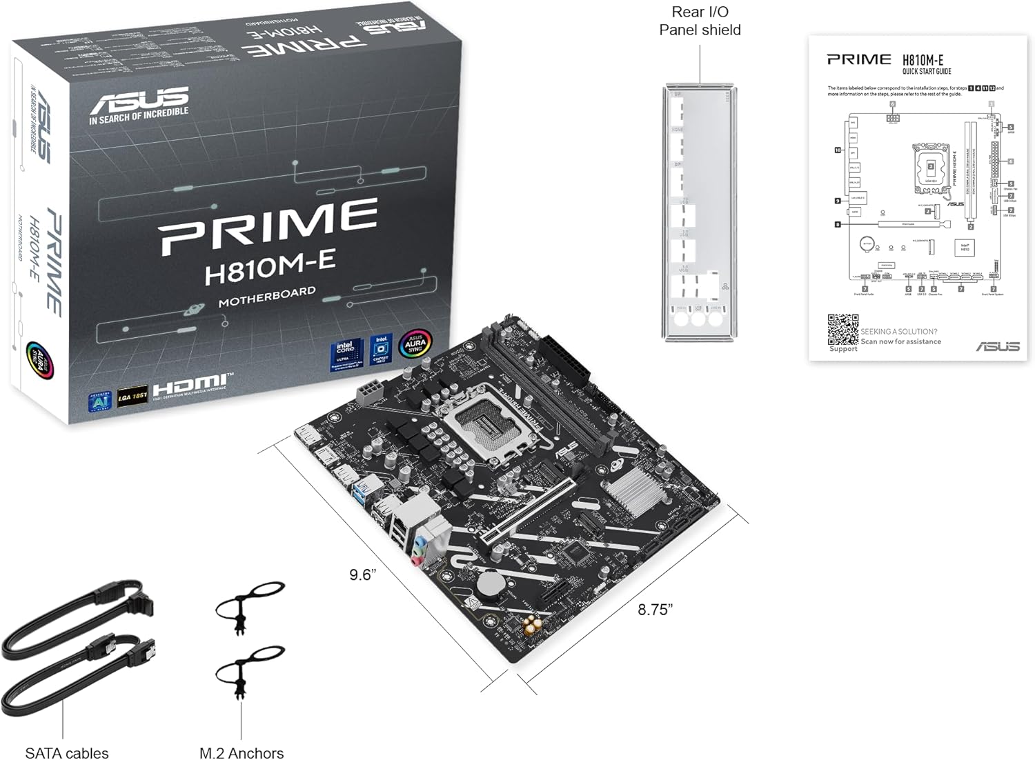
Package Contents
Verify that all items are present in your motherboard package:
- ASUS Prime H810M-E-CSM Motherboard
- SATA 6Gb/s Data Cables (2x)
- M.2 SSD Anchors (2x)
- Rear I/O Shield
- User Manual / Quick Start Guide
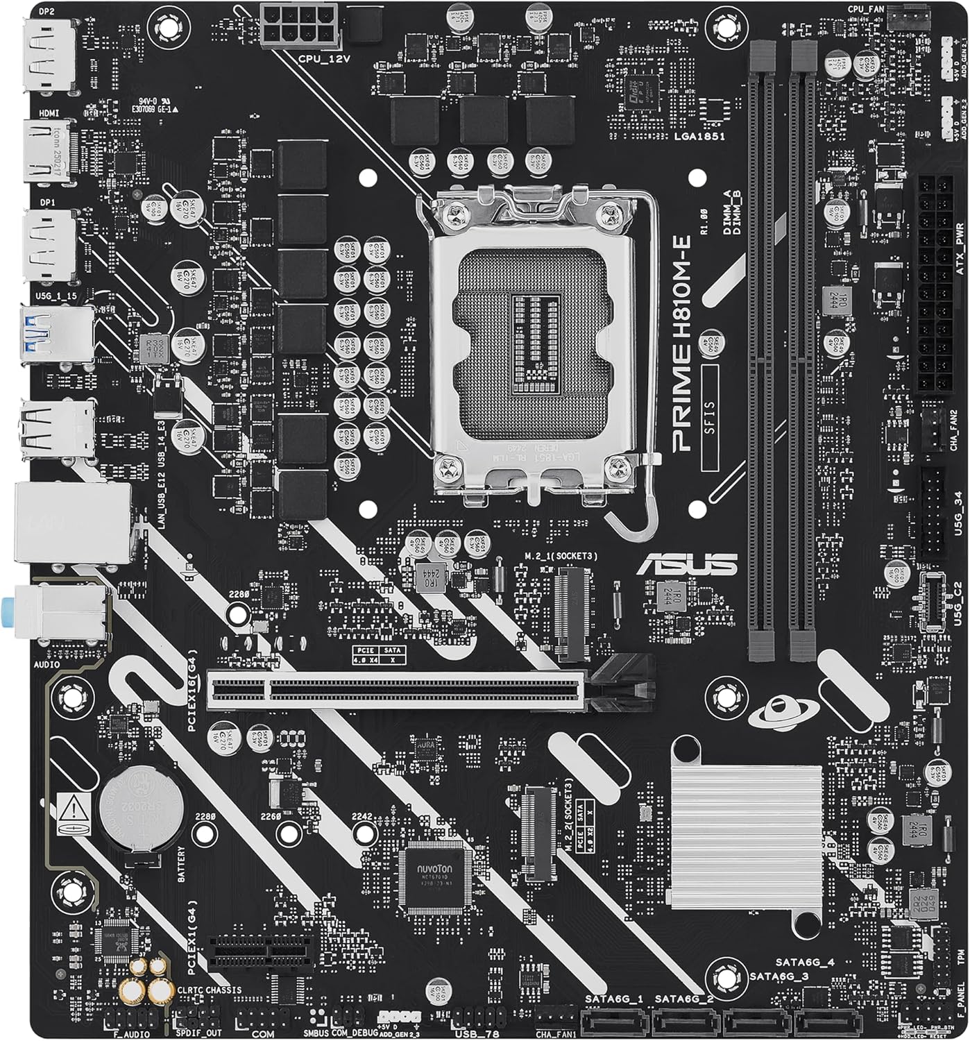
Motherboard Layout
Familiarize yourself with the key components and connectors on the motherboard.

Setup
1. CPU Installation
This motherboard supports Intel Core Ultra (Series 2) processors with an LGA 1851 socket.
- Open the CPU socket lever and remove the protective cap.
- Carefully align the CPU with the socket, ensuring the notches on the CPU match the keys on the socket.
- Gently place the CPU into the socket without applying force.
- Close the socket lever to secure the CPU.
- Install the CPU cooler according to its manufacturer's instructions.
2. Memory (RAM) Installation
The motherboard features two DDR5 DIMM slots, supporting up to 128GB of RAM.
- Open the clips at both ends of the DIMM slot.
- Align the memory module with the slot, ensuring the notch on the module matches the key in the slot.
- Press down firmly on both ends of the memory module until the clips snap into place.
3. Storage Installation
The motherboard supports M.2 SSDs and SATA drives.
M.2 SSD Installation:
- Locate the M.2 slot on the motherboard.
- Insert the M.2 SSD into the slot at a 30-degree angle.
- Gently push down the SSD and secure it with the provided M.2 anchor or screw.

SATA Drive Installation:
- Connect one end of a SATA data cable to a SATA port on the motherboard.
- Connect the other end of the SATA data cable to your storage drive (HDD/SSD).
- Connect a SATA power cable from your power supply unit (PSU) to the storage drive.
4. PCIe Card Installation
Install graphics cards or other expansion cards into the PCIe 4.0 slots.
- Open the retention clip at the end of the PCIe slot.
- Align the expansion card with the slot and press down firmly until it is seated and the clip snaps shut.
- Secure the card to the PC case with a screw.

5. Power Connections
Connect the power supply unit (PSU) cables to the motherboard.
- 24-pin ATX Power Connector: Connect the main 24-pin power cable from your PSU to the corresponding connector on the motherboard.
- 8-pin CPU Power Connector (EATX12V): Connect the 8-pin CPU power cable from your PSU to the connector located near the CPU socket.
6. Front Panel Connections
Connect your PC case's front panel cables (power button, reset button, USB ports, audio jacks, LED indicators) to the corresponding headers on the motherboard. Refer to the motherboard diagram for exact locations.
Operating
First Boot and BIOS/UEFI Setup
After assembling your system, connect a monitor, keyboard, and mouse. Power on the system.
- Press the Delete key during startup to enter the BIOS/UEFI setup utility.
- Configure boot order, system time, and other essential settings.
- Save changes and exit the BIOS.

Driver and Operating System Installation
Install your preferred operating system (e.g., Windows 10/11) from a bootable USB drive or DVD. After OS installation, install the latest drivers for the motherboard chipset, LAN, audio, and any other integrated components from the ASUS support website to ensure optimal performance and stability.
Maintenance
Cleaning
Regularly clean your PC to prevent dust buildup, which can lead to overheating and component failure. Use compressed air to remove dust from heatsinks, fans, and other components. Ensure the system is powered off and unplugged before cleaning.
BIOS Updates
Periodically check the ASUS support website for BIOS updates. BIOS updates can improve system stability, compatibility, and performance. Follow the instructions provided by ASUS carefully when performing a BIOS update to avoid system damage.
Troubleshooting
This section addresses common issues you might encounter.
- No Display / No Post:
- Ensure all power cables (24-pin ATX, 8-pin CPU) are securely connected.
- Reseat the RAM modules. Try booting with only one RAM stick.
- Verify the CPU is correctly seated and the CPU cooler is properly installed.
- Check that the graphics card is fully seated in its PCIe slot and has adequate power.
- If using integrated graphics, ensure your monitor is connected to the motherboard's video output (HDMI).
- System Instability / Crashes:
- Ensure all drivers are up to date.
- Check CPU and GPU temperatures using monitoring software.
- Run memory diagnostic tools to check for faulty RAM.
- Verify PSU wattage is sufficient for all components.
- Peripheral Not Detected:
- Try connecting the peripheral to a different port.
- Install or update drivers for the peripheral.
- Check BIOS settings to ensure the port is enabled.
Specifications
| Feature | Specification |
|---|---|
| Brand | ASUS |
| Model Name | PRIME H810M-E-CSM |
| CPU Socket | LGA 1851 |
| Compatible Processors | Intel Core Ultra Processors (Series 2) |
| Chipset Type | Intel H810 |
| RAM Memory Technology | DDR5 |
| Memory Slots Available | 2 |
| Ram Memory Maximum Size | 128 GB |
| Graphics Card Interface | PCI Express 4.0 |
| Total PCIe Ports | 2 |
| Total SATA Ports | 4 |
| Total M.2 Slots | 1 |
| Total USB Ports | 11 (various types) |
| Total Number of HDMI Ports | 1 |
| Number of Ethernet Ports | 1 (1Gb LAN) |
| Main Power Connector Type | 24-Pin |
| Platform | Windows 10, Windows 11 |
| Item Dimensions L x W x H | 9.6"L x 8.7"W x 1.5"H |
| Item Weight | 1.1 Pounds |
Warranty Information
The ASUS Prime H810M-E-CSM Motherboard comes with a 3-year manufacturer's warranty. For detailed terms and conditions, please refer to the warranty card included in your package or visit the official ASUS support website.
Support
For further assistance, technical support, driver downloads, or BIOS updates, please visit the official ASUS support website:
You can also find additional resources and FAQs on the ASUS product page for the Prime H810M-E-CSM.