1. Introduction
The SOSODBBM TAC4371CT series products are advanced three-phase installation multi-function energy meters designed for comprehensive power parameter measurement and analysis. This meter is ideal for monitoring photovoltaic inverters, statistical analysis of energy consumption, and power monitoring in utilities and intelligent buildings. Its robust communication capabilities make it suitable for various control systems, SCADA systems, and energy management systems.
This manual provides essential information for the safe and efficient installation, operation, and maintenance of your TAC4371CT energy meter.
2. Product Features
- Three-Phase Measurement: Designed for three-phase electrical systems.
- Multi-Function Energy Monitoring: Measures and analyzes various power parameters including voltage, current, four-quadrant power, power factor, and harmonic content.
- Energy Consumption Statistics: Provides measurement of two-way active energy, reactive energy, and monthly/daily electricity consumption statistics.
- Wide Application: Suitable for photovoltaic inverter monitoring, energy consumption analysis, and power monitoring in utilities and smart buildings.
- Communication Interface: Equipped with a 2-wire RS485 interface for integration into control and energy management systems.
- LCD Display: Clear display for easy reading of measured values.
3. Package Contents
Verify that all items listed below are present and undamaged upon opening the package:
- 1 × TAC4371CT Three Phase Energy Meter
- 3 × Current Transformers (CTs) (e.g., 100A CTs for the "Meter with 100ACT" variant)

Figure 3.1: TAC4371CT Energy Meter and included Current Transformers (CTs).
4. Specifications
| Parameter | Value |
|---|---|
| Model Number | TAC4371CT |
| Frequency | 45 ~ 65 Hz |
| Rated Voltage (L-N) | 230 Vac |
| Rated Voltage (L-L) | 400 Vac |
| Measured Voltage Range (L-N) | 30 to 300 Vac |
| Measured Voltage Range (L-L) | 30 to 500 Vac |
| Total Active Energy Range | 0 to 99999999.999 kWh |
| Interfaces Standard | 2-wire RS485 |
| Baud Rate (default) | 9600 bps |
| Dimensions | 72 x 100 x 66 mm |
| Operating Temperature | -25 to +55 °C |
| Accuracy Class | 1 |
| Max Operating Current | 50A - 79A (Note: CT rating varies by variant, e.g., 100A, 150A, 200A) |
| Power Supply | AC |
| Display Type | LCD |

Figure 4.1: Physical dimensions of the TAC4371CT Energy Meter.
5. Safety Information
Please read and understand all safety instructions before installing or operating the TAC4371CT energy meter. Failure to follow these instructions may result in electric shock, fire, or serious injury.
- Qualified Personnel: Installation and maintenance should only be performed by qualified electrical personnel.
- Power Disconnection: Always disconnect power to the circuit before installing, wiring, or servicing the meter.
- Proper Wiring: Ensure all wiring connections are secure and comply with local electrical codes and standards.
- Environmental Conditions: Do not expose the meter to moisture, extreme temperatures outside its operating range, or corrosive environments.
- CT Installation: Ensure Current Transformers (CTs) are installed correctly with the proper orientation and securely connected to the meter. Incorrect CT installation can lead to inaccurate readings or damage.
6. Setup and Installation
The TAC4371CT is designed for DIN rail installation. Follow these steps for proper setup:
- Mounting: Securely mount the energy meter onto a standard DIN rail in an appropriate electrical enclosure.
- Power Wiring: Connect the three-phase voltage inputs (L1, L2, L3, N) to the corresponding terminals on the meter. Refer to the wiring diagram on the meter or in the detailed product documentation for exact terminal assignments.
- Current Transformer (CT) Connection:
- Install the three CTs around the respective phase conductors (L1, L2, L3). Ensure the CTs are oriented correctly according to the arrow on the CT, indicating the direction of current flow.
- Connect the secondary wires of each CT to the corresponding current input terminals on the meter (e.g., S1/S2 for each phase).
- Ensure all CT connections are tight and secure.
- RS485 Communication (Optional): If using the RS485 interface, connect the A and B data lines to the RS485 terminals on the meter. Ensure proper polarity.
- Power On: After verifying all connections are correct and secure, restore power to the circuit. The meter's LCD display should illuminate.

Figure 6.1: Rear view of the TAC4371CT meter, illustrating terminal blocks for wiring connections.
7. Operating Instructions
Once powered on, the TAC4371CT meter will begin measuring and displaying various electrical parameters on its LCD screen.
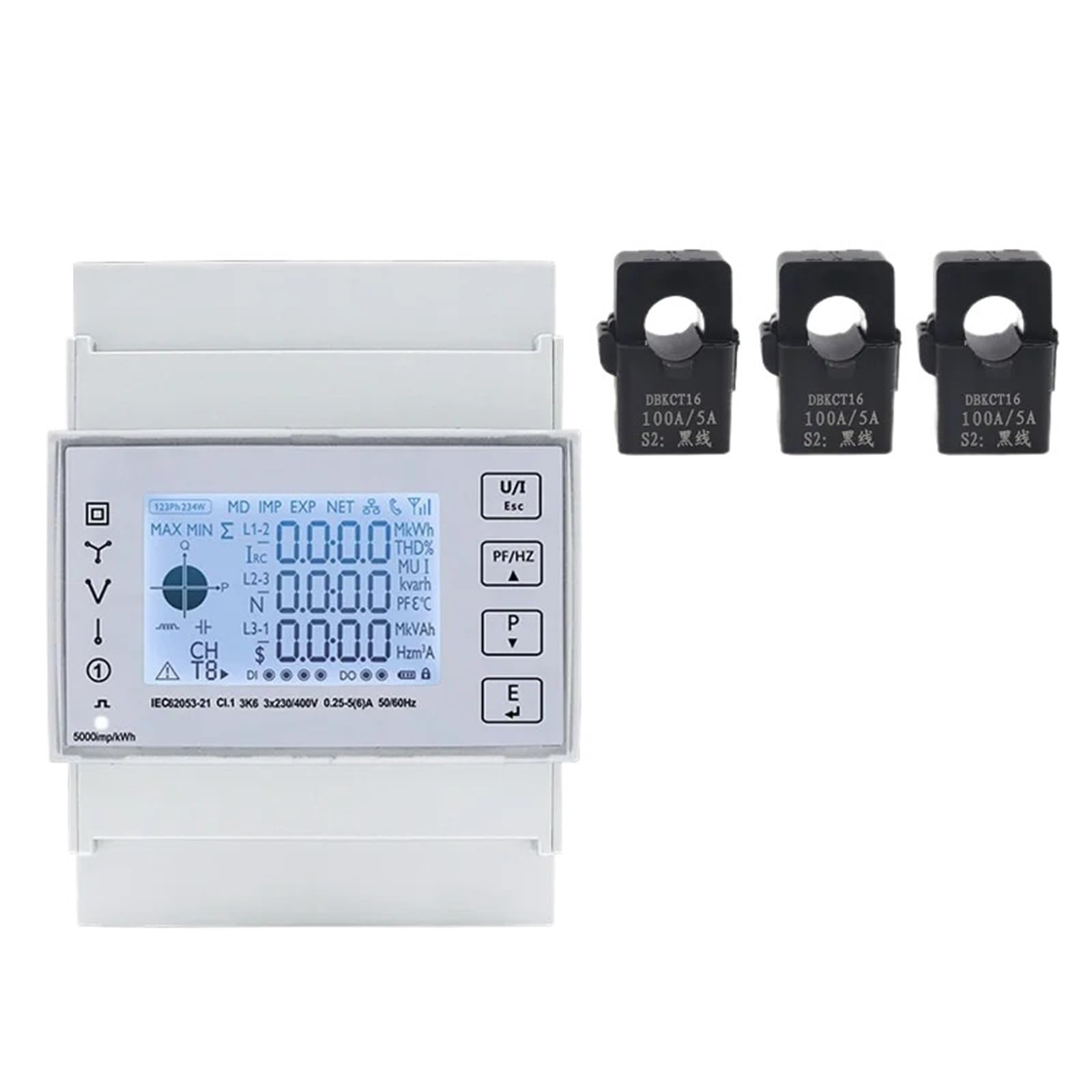
Figure 7.1: Front panel of the TAC4371CT meter with LCD display and control buttons.
7.1. Display Navigation
The meter typically cycles through various measurement screens automatically. Use the buttons on the front panel to manually navigate through different parameters or access settings.
- Up/Down Arrows: Navigate between different display screens (e.g., voltage, current, power, energy).
- "E" Button: Often used to enter or confirm selections in menu modes.
- "P" Button: May be used for page switching or parameter selection.
- "U/T" Button: Could be for unit selection or total energy display.
Refer to the detailed programming guide (if available) for advanced configuration and specific button functions.
7.2. Measured Parameters
The meter can display a wide range of parameters, including but not limited to:
- Line-to-Neutral Voltage (L-N)
- Line-to-Line Voltage (L-L)
- Phase Current (A)
- Active Power (kW)
- Reactive Power (kVar)
- Apparent Power (kVA)
- Power Factor (PF)
- Frequency (Hz)
- Total Active Energy (kWh)
- Total Reactive Energy (kVarh)
- Harmonic Content (THD)
7.3. RS485 Communication
The RS485 interface allows remote monitoring and data acquisition. The default baud rate is 9600 bps. For detailed communication protocols and register addresses, consult the specific communication protocol documentation for the TAC4371CT series.
8. Maintenance
The TAC4371CT energy meter is designed for long-term, reliable operation with minimal maintenance. However, periodic checks can help ensure optimal performance.
- Cleaning: Keep the meter's display and casing clean. Use a soft, dry cloth. Do not use abrasive cleaners or solvents.
- Connection Checks: Periodically inspect all wiring connections for tightness and signs of corrosion or damage. Ensure CTs are securely in place.
- Environmental Inspection: Ensure the operating environment remains within the specified temperature and humidity ranges.
- Firmware Updates: Check the manufacturer's website for any available firmware updates, though this typically requires specialized tools and procedures.
Note: There are no user-serviceable parts inside the meter. Do not attempt to open the casing.
9. Troubleshooting
If you encounter issues with your TAC4371CT energy meter, refer to the following common problems and solutions:
| Problem | Possible Cause | Solution |
|---|---|---|
| Meter display is blank | No power supply; incorrect wiring. | Check power connections to the meter. Ensure rated voltage is supplied. Verify wiring according to the diagram. |
| Inaccurate readings | Incorrect CT installation (orientation, connection); incorrect wiring; meter fault. | Verify CT orientation (arrow direction). Check CT secondary wiring to the meter. Ensure voltage wiring is correct. If problem persists, contact support. |
| RS485 communication failure | Incorrect wiring (A/B polarity); incorrect baud rate; software configuration issue. | Check RS485 wiring polarity. Confirm baud rate (default 9600 bps) and other communication settings in your software. |
| Meter not responding to buttons | Temporary software glitch; button malfunction. | Try power cycling the meter (disconnect and reconnect power). If buttons remain unresponsive, contact support. |
If the issue is not resolved by the above steps, please contact customer support.
10. Warranty and Support
10.1. Warranty Information
SOSODBBM products are manufactured to high-quality standards. For specific warranty terms and conditions, please refer to the warranty card included with your product or visit the official SOSODBBM website. The warranty typically covers defects in materials and workmanship under normal use for a specified period from the date of purchase.
Note: The warranty does not cover damage caused by improper installation, misuse, unauthorized modifications, or natural disasters.
10.2. Customer Support
For technical assistance, troubleshooting, or warranty claims, please contact SOSODBBM customer support. When contacting support, please have your product model number (TAC4371CT) and purchase information readily available.
- Website: Visit the official SOSODBBM website for FAQs, additional documentation, and contact information.
- Email/Phone: Refer to your product packaging or the official website for the most current contact details.